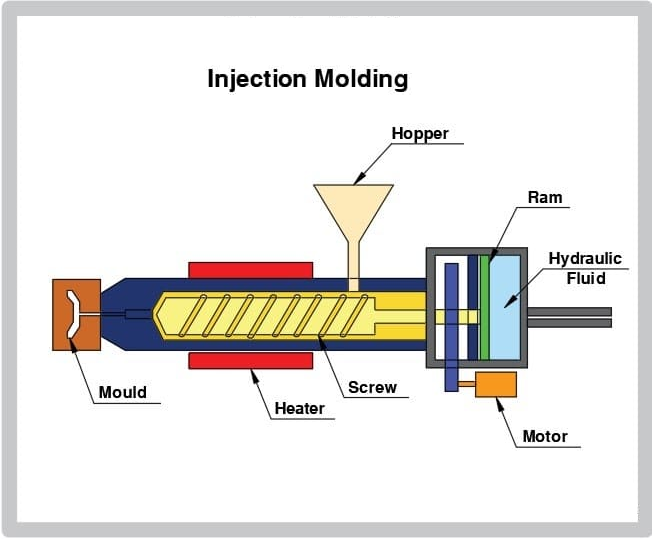
Ejector marks are common defects in the injection molding process, which seriously affect the quality and appearance of molded parts. In order to eliminate its influence, we need to understand its cause first.
The resulting thimble marks can be concave or convex into the plastic surface. Most modern manufacturers will go to great lengths to hide these marks as they can seriously detract from surface detail and spoil the overall effect on the modeller. As a result, these marks are usually located on the underside of the part or in other locations that cannot be seen once the model is finished.
To avoid ejector pin marks in injection molded parts, follow these structured solutions, addressing design, process, material, and maintenance factors:
Ways to Avoid Ejector Pin Marks in Injection Molds
You need more detailed guidance, right? Let’s look down.
From the beginning of the mold design of injection molding products, we need to start with the main issues listed below.
- Optimize Mold Design
- Adjust Process Parameters
- Material Considerations
- Part Design Modifications
- Maintenance & Tooling Care
- Advanced Solutions
Optimize Mold Design
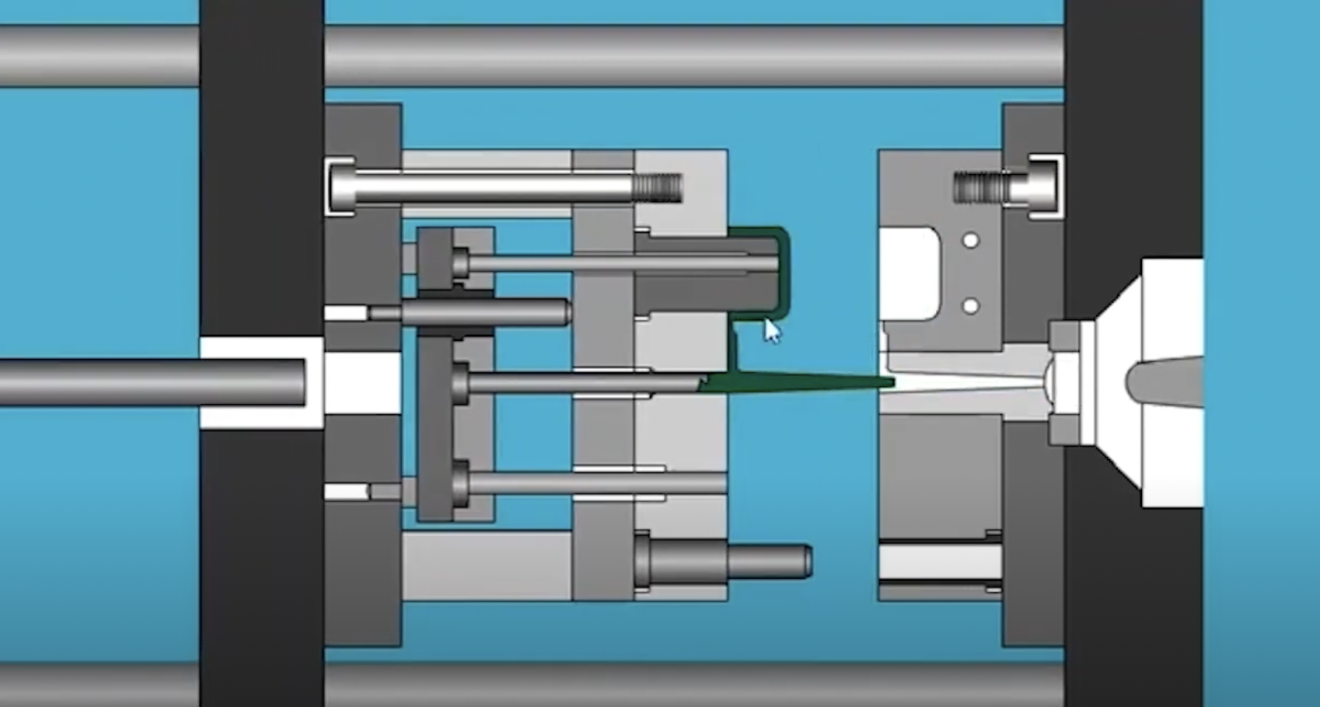
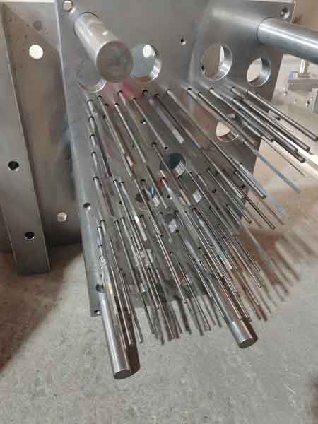
- Increase Number of Ejector Pins: Distribute ejection force evenly to reduce pressure on individual pins.
- Strategic Pin Placement:
- Position pins under ribs, bosses, or thicker sections for structural support.
- Avoid placing pins near cosmetic surfaces or thin walls.
- Use Alternative Ejection Systems:
- Sleeve Ejectors: For cylindrical parts (e.g., bottle caps).
- Blade Ejectors: For long, flat parts (e.g., panels).
- Stripper Plates: Distribute force across the entire part edge.
- Textured or Tapered Pins: Reduce contact friction with polished or micro-textured surfaces.
Adjust Process Parameters
- Control Ejection Speed/Force:
- Use gradual, low-pressure ejection to minimize stress.
- Program multi-stage ejection (e.g., slow initial push followed by faster retraction).
- Optimize Cooling:
- Ensure uniform cooling to prevent warping/sticking.
- Use conformal cooling channels near ejection points.
- Delay Ejection Time: Allow the part to cool sufficiently before ejection to reduce softness.
Material Considerations
- Select Low-Shrinkage Materials: Minimize part adhesion to the mold (e.g., ABS, PP).
- Add Mold Release Agents: Use internal or external lubricants (e.g., silicone sprays) cautiously (avoid for food/medical parts).
- Avoid Over-Packing: Excessive injection pressure increases part adhesion.
Part Design Modifications
- Add Draft Angles: 1–3° draft angles ease ejection and reduce required force.
- Reinforce Ejection Areas: Design thicker sections or ribs under pin locations.
- Minimize Undercuts: Simplify geometry to reduce ejection resistance.
Maintenance & Tooling Care
- Inspect Ejector Pins Regularly:
- Replace worn, bent, or corroded pins.
- Ensure pins are aligned and move freely without binding.
- Polish Mold Cavities: Smooth surfaces reduce part adhesion and ejection force.
Advanced Solutions
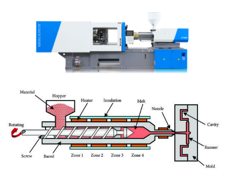
- Gas-Assisted Ejection: Use compressed air to gently separate the part from the mold.
- Simulation Tools:
- Conduct mold flow analysis (e.g., Autodesk Moldflow) to predict stress points and optimize pin placement.
- Validate ejection force requirements before production.
Example Workflow
- Design Phase:
- Simulate ejection forces and place pins in robust areas.
- Add 2° draft angles to all vertical walls.
- Mold Setup:
- Install stripper plates for flat parts or sleeve ejectors for round parts.
- Use polished, hardened steel pins.
- Process Tuning:
- Set ejection pressure to 10–20% of clamping force.
- Delay ejection by 2–3 seconds for additional cooling.
- Post-Production:
- Inspect pins weekly for wear.
- Adjust cooling time if part warping occurs.
Common Pitfalls to Avoid
- Overloading Pins: Using too few pins concentrates force, causing marks.
- Ignoring Draft Angles: Poor draft design increases ejection resistance.
- High Mold Temperatures: Softens the part, increasing adhesion.
By integrating these strategies, you can minimize or eliminate Injection Ejector Pin marks while maintaining production efficiency.
Injection molding mould ejector pin design
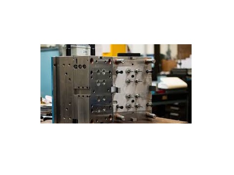
Design of Ejection Pins for Injection Molding Molds
Ejector pins (or knockout pins) are critical for part ejection without damaging the mold or product. Key considerations include:
- Types and Material Selection
- Positioning and Quantity Optimization
- Dimensions and Geometry
- System Integration and Cooling
- Simulation and Process Adaptation
- Special Scenarios
- Manufacturing and Maintenance
Types and Material Selection
- Types:
- Straight pins: Simple and cost-effective for basic molds.
- Stepped pins: Distribute stress in complex molds, reducing part deformation.
- Floating pins: Allow micro-displacements for tight-tolerance or shrink-prone parts.
- Sleeve pins: Ideal for deep holes or uniform force distribution.
- Materials: Use wear-resistant alloys like nitrided H13 steel, tungsten carbide, or hardened tool steels for durability.
Positioning and Quantity Optimization
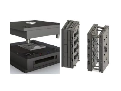
- Near gates: Increase pin density to counteract melt pressure.
- High-resistance areas: Prioritize ribs, undercuts, or complex geometries.
- Aesthetic zones: Hide pin marks in non-critical areas (e.g., hidden edges).
- Simulation-driven: Use Moldflow or similar tools to balance quantity and minimize part warpage.
Dimensions and Geometry
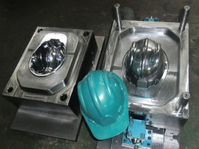
- Diameter: Larger diameters (≥2.5mm) reduce bending; standardize sizes for simplicity.
- Length: Ensure full part ejection without interference.
- Tip design: Rounded or tapered tips minimize surface marks.
System Integration and Cooling
- Ejection system: Synchronize pins with ejector plates, return pins, and guides.
- Cooling channels: Integrate cooling near pins to avoid thermal distortion.
Simulation and Process Adaptation
- Moldflow analysis: Predict part shrinkage and optimize Injection Ejector Pin placement.
- Material-specific adjustments: Tolerances for shrinkage (e.g., delayed ejection for high-shrink polymers).
Special Scenarios
- Thin-walled parts: Use stripper plates or sleeves to avoid deformation.
- Undercuts: Combine angled pins or side-core mechanisms for complex geometries.
Manufacturing and Maintenance
- Standardization: Reduce pin variations to streamline maintenance.
- Guiding bushings: Ensure precision and extend mold life.
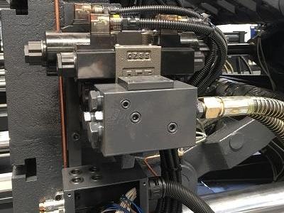
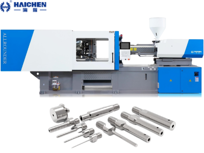
Haichen injection molding machine Ejector pin
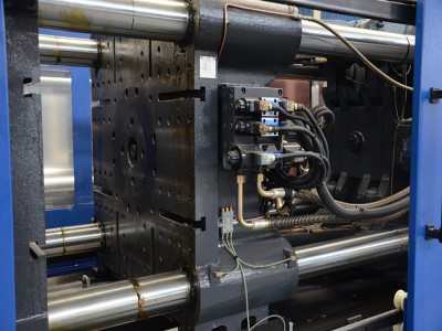
- Function and Standards of Ejector Pins
- Compatibility of Haichen’s Ejector Pin System
- After-Sales Support and Maintenance
- Application Guidelines
- Model Selection and Customization
Function and Standards of Ejector Pins
Ejector pins are critical components of the mold ejection system, designed to release finished products from the mold after injection. According to the Chinese national standard GB/T 8847—2003 (Terminology for Die-Casting Molds), ejector pins are classified as standard mold components (Code 3.6.1). Common types include:
- Standard Ejector Pins: Cylindrical steel rods driven by the ejector plate.
- Vented Ejector Pins: Feature machined vent grooves on the side to prevent air entrapment and product defects.
- Custom-Shaped Ejector Pins: Such as inclined ejector pin units for complex mold geometries.
Compatibility of Haichen’s Ejector Pin System
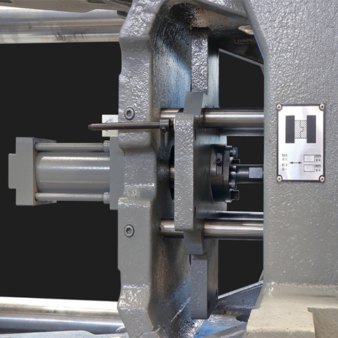
Haichen’s injection molding machines are designed to support industry-standard ejection systems, though detailed parameters are not explicitly stated in their technical documentation. Key considerations include:
- Alignment: Ejector pins must align with the mold’s knockout plate for precise operation.
- Tie-Bar Spacing: Machine tonnage determines tie-bar spacing (e.g., 470×470mm for the E-Series), which indirectly affects ejector pin layout.
- Ventilation Optimization: Haichen emphasizes mold venting; vent grooves on ejector pins must comply with depth and length standards (typically ≤0.03mm for groove depth).
After-Sales Support and Maintenance
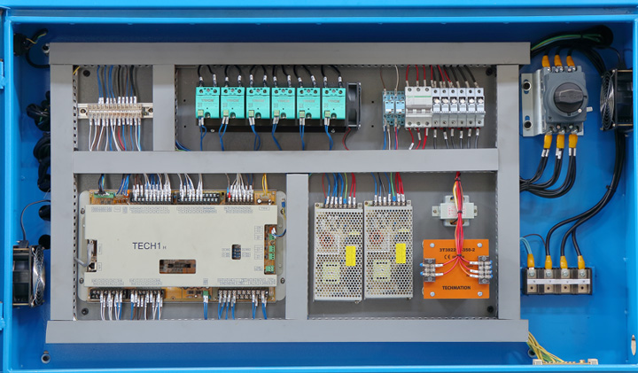
Haichen provides warranty and technical support for ejector pins under specific conditions:
- Warranty Coverage: Free replacement if damage occurs under normal operation (e.g., correct material usage, proper maintenance).
- Technical Assistance: On-site engineer support is available, with costs shared depending on the issue’s root cause.
- Exclusions: Damage caused by misuse (e.g., incomplete pin retraction leading to mold crushing) is not covered.
Application Guidelines
- Mold Design: Optimize ejector pin quantity and placement based on machine specifications (tonnage, tie-bar spacing) and include vent channels.
- Production Monitoring: Track ejector pin marks; these may become more pronounced as molds wear, requiring regular maintenance.
- Troubleshooting: For issues like pin jamming or vent blockages, contact Haichen for spare parts or adjustment recommendations.
Model Selection and Customization
Ejector pin systems vary across Haichen models (e.g., E-Series, HCS-Series). Users should provide mold dimensions or application details (e.g., thin-wall packaging, daily goods) for tailored recommendations. For example, producing pens requires sufficient ejector stroke and uniform pin distribution to prevent deformation.
Haichen’s ejector pin systems adhere to industry standards, requiring users to align mold design with machine specifications (tonnage, tie-bar spacing) and follow operational guidelines. Haichen offers technical support and warranty services for compliant use. For detailed parameters, consult the machine manual or contact Haichen engineers directly.

By the end
Injection Ejector Pin design balances part quality, mold longevity, and cost. Leverage simulations, material expertise, and collaboration with mold engineers to refine layouts and avoid defects. Focus on system integration and cooling to ensure smooth, repeatable ejection cycles.