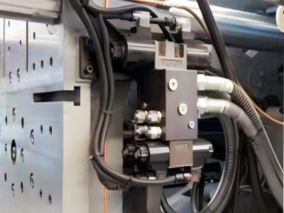
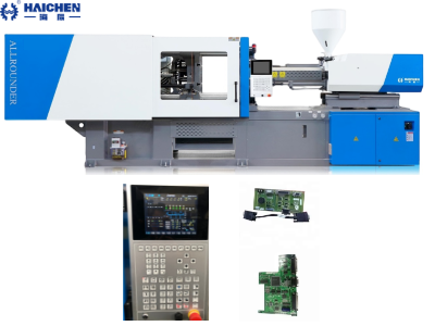
Hydraulic safety device of the injection molding machine is a piece of equipment used to protect the hydraulic system from abnormal conditions such as overpressure or underpressure during operation.
Its main function is to control the pressure of the hydraulic system.
To ensure the safe operation of the equipment and prevent equipment damage or operator injury caused by hydraulic system failure.
Specifically, hydraulic safety devices include hydraulic safety valves, relief valves, etc.
These devices can detect the pressure of the hydraulic system and automatically open.
When the pressure exceeds the set range to release excess hydraulic energy, thereby preventing system overload or damage.
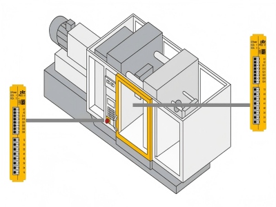
In addition, hydraulic safety devices can also be linked with mechanical and electrical protection devices.
For instance, they can interrupt the hydraulic circuit through mechanical stop blocks or electrical switches, further enhancing safety.
The main function of the hydraulic safety device for injection molding machines is to monitor and adjust the pressure of the hydraulic system.
To ensure that the equipment operates within a safe range and reduce potential safety hazards caused by hydraulic system failures.
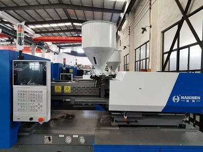
The types and working principles of hydraulic safety devices for injection molding machines
The hydraulic safety device in injection molding machines primarily functions to prevent equipment damage and personal injury by addressing three critical factors: system overload, abnormal pressure fluctuations, and operational errors.
Specifically, it detects excessive load conditions, stabilizes sudden pressure changes, and minimizes risks from user errors.
Thereby ensuring safe operation of the machinery.
- Sliding valve type hydraulic safety valve
- Standard type hydraulic safety valve
- Active hydraulic safety valve
- Relief valve
- One-way throttling type safety valve
- Other safety devices
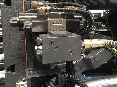
Sliding valve type hydraulic safety valve
Principle: The on-off of the oil circuit is controlled by the sliding of the valve core.
The structure is simple and compact, and no external control valve is required.
Applicable scenarios:Small flow and small injection molding machines, often used for safety protection of the opening and closing mold oil circuit.
Features:The valve core status is monitored through an electronic position sensor.
When an abnormality occurs, a feedback signal is sent to the main control computer to block subsequent actions.
Standard type hydraulic safety valve
Principle:Integrates position sensors, induction coils and directional cartridge valves, and uses pilot pressure to control the opening and closing of the main valve core.
Features:It can achieve oil circuit blocking through remote control, meet the requirements of export certification, and is suitable for main oil circuit protection.
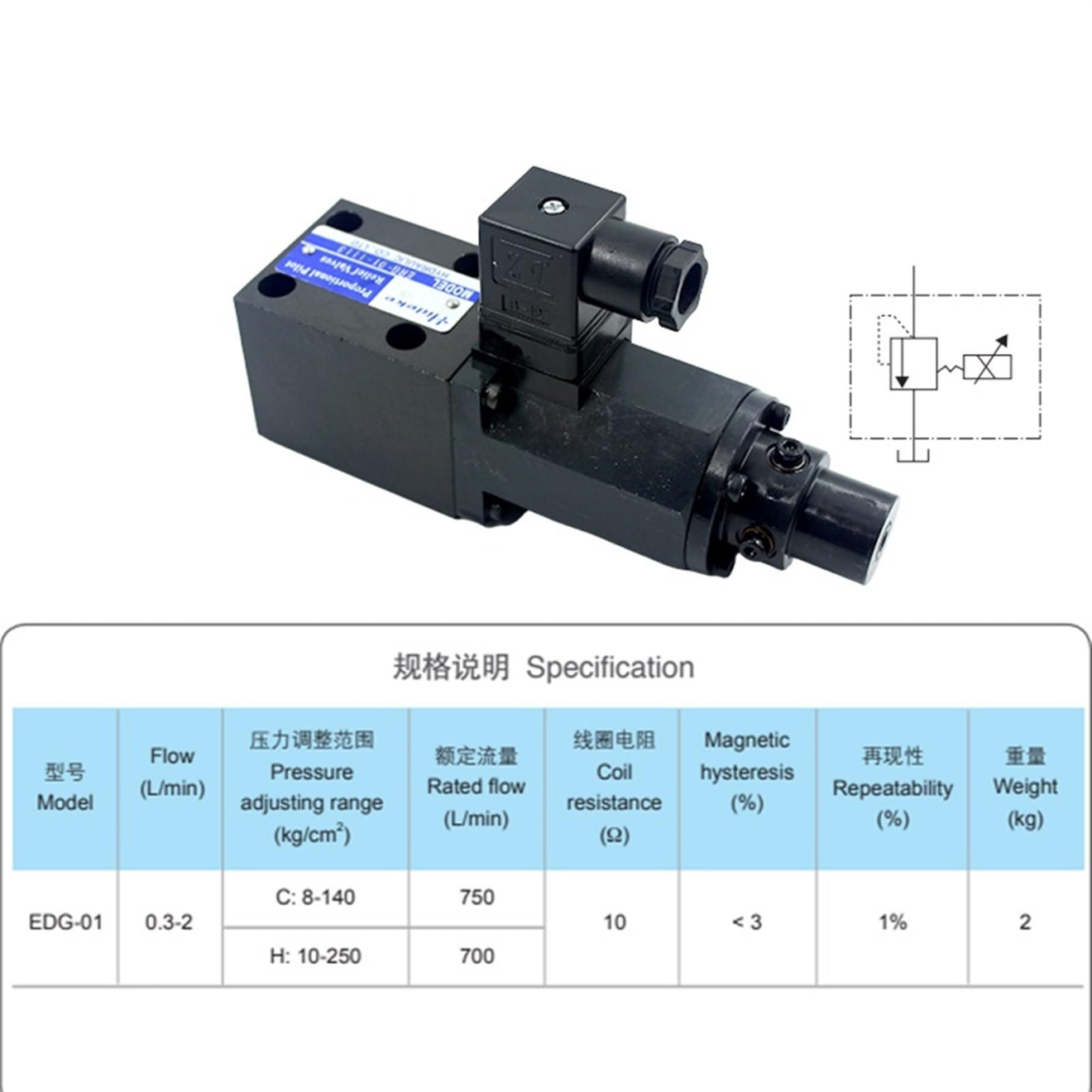
Active hydraulic safety valve
Principle:Add a control port (Z port) to forcibly open the valve core to reduce the opening pressure and response time.
Advantage:Even if it is shut down in an emergency, it can still immediately respond to the mold-opening command, maximizing personal safety.
Relief valve
Principle:When the system pressure exceeds the set value, the valve core is lifted, and the excess oil flows back to the oil tank to maintain pressure stability.
Classification:Direct-acting type (direct spring balance) and pilot-operated type controlling the main valve core through a pilot valve.
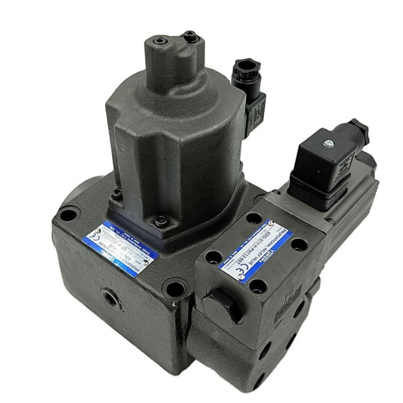
One-way throttling type safety valve
Principle:By combining the functions of a check valve and a throttle valve.
It restricts the unidirectional flow of oil and regulates the flow rate to prevent reverse impact.
Other safety devices
Balanced orifice plate safety valve
Principle: The position of the valve core is adjusted by the lever action.
It is suitable for large-diameter pipelines, with sensitive action but relatively large volume.
Pilot-operated piston safety valve
Principle: The piston movement is controlled by a pilot valve, which is suitable for high-pressure systems and has a fast response speed.
Pulse-type safety valve
Principle: Rapidly release pressure through pulse signals to prevent instantaneous overload.
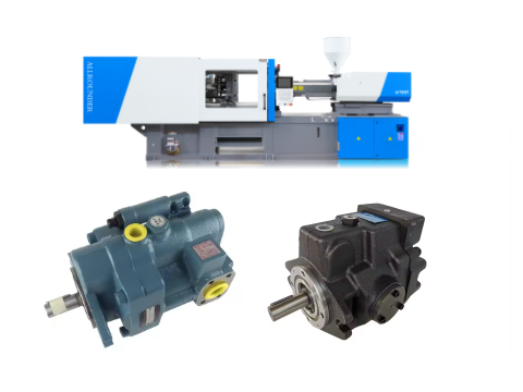
In-depth analysis of Working principle
- Dynamic response of the relief valve
- Hydraulic interlock logic
Dynamic response of the relief valve
Direct-acting type:
The spring force directly balances the oil pressure.
It has a fast response but low accuracy and is suitable for small flow systems.
Pilot-operated type:
The main valve core is controlled by a pilot valve, with a pressure deviation of less than 2%, suitable for high-pressure and high-flow scenarios.
Pressure relief process:
When the pressure exceeds the set value, the displacement of the valve core Δx=√(2k(P-P_set)/A).
Where k is the spring stiffness and A is the area of the valve core.
Hydraulic interlock logic
Mechanical interlocking:
When the safety door is closed, if the displacement of the transmission rod is ≥8mm, it triggers the valve core to act.
Electrical linkage:
After the PLC detects the limit switch signal of the safety door, it outputs a valve control signal with a delay of less than 50ms.
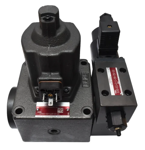
Installation location and system integration
- Main oil line protection
- Monitoring of key nodes
Main oil line protection
The hydraulic system typically integrates the relief valve into the pump’s outlet pipeline.
For example, in the AZ560 model, technicians configure the main relief valve to operate at 14MPa, while the safety valve functions at 17MPa.
Additionally, engineers prioritize installing the active safety valve within the mold’s opening/closing oil circuit.
Specifically to accelerate emergency shutdown response times.
Monitoring of key nodes
Nozzle pressure sensor
When installed embedded, it is necessary to ensure that it is flush with the surface of the flow channel, with an error of less than 0.02mm.
Two-position two-way valve for locking mold oil circuit: Installed within 50cm of the oil inlet of the oil cylinder, the pipe diameter matching error is ≤±10%.
Redundant design
High-end models implement a three-tier protection system– comprising a mechanical stop block (coarse level).
Followed by a hydraulic interlock (medium level), and finally grating detection (fine level) .
While the system dynamically maintains the time difference between response level progression within 200 milliseconds.
Hydraulic safety common faults and failure modes
- Oil spill
- Abnormal pressure
- The valve core is stuck or worn
- The oil temperature is too high
- Failure of electronic components
Oil spill
Reasons: Aging of seals, loose joints, and worn valve bodies.
Impact: Internal leakage leads to a drop in system pressure.
While external leakage pollutes the environment and increases energy consumption.
Abnormal pressure
No pressure or insufficient pressure: oil pump wear, relief valve jamming, oil contamination.
Pressure fluctuation: Air mixed into the system, wear of the proportional valve.
And excessive oil temperature causing changes in viscosity.
The valve core is stuck or worn
Reasons: Sedimentation of impurities in the oil, fatigue deformation of the spring, improper fit clearance between the valve core and the valve seat.
Manifestations: Action delay, failure of flow regulation.
The oil temperature is too high
Reasons: Cooling system failure such as filter screen blockage, insufficient cooling water.
Frequent opening of the relief valve, internal leakage of the oil pump.
Consequence: Accelerate the aging of seals and reduce system efficiency.
Failure of electronic components
Position sensor failure: Leads to misjudgment of the safety valve status and fails to promptly block dangerous actions.