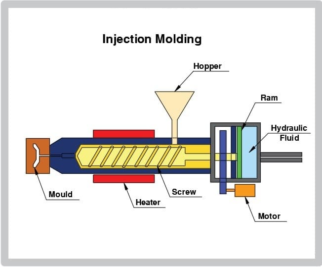
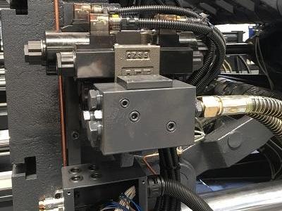
The injection molding machine has an emergency stop button on the operating side and one on the non-operating side. Pressing it can quickly stop the machine and cut off the power supply to the motor. The electrical safety module is integrated here, so the emergency stop will directly cut off the power supply, which is a key point.
Emergency stop systems need to be easily accessible, and injection molding regular safety inspections and operator training are important, which means the location and operability of the emergency stop button is important.
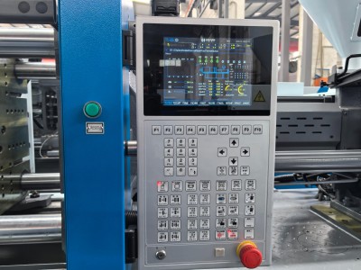
When an accident or error occurs during the injection molding operation, first press the emergency stop button (usually a red button located in the lower right corner of the screen), then turn off the main power supply and restart after troubleshooting.
Injection Molding Machine Emergency Stop Function Test Procedure
- Preparation and Safety Verification
- Emergency Stop Activation Test
- Integrated System Coordination Test
- Failure Mode Simulation
- Reset and Restart Validation
- Documentation and Compliance
Preparation and Safety Verification
- Equipment Status Check: Ensure the machine is in standby mode with no personnel or obstructions in the mold area.
- Safety Device Validation: Confirm the safety door interlock is functional (e.g., mold movement is disabled when the door is open).
- System Initialization: Verify normal operation of hydraulic pressure, temperature sensors, and other parameters after power-on.
Emergency Stop Activation Test
- Trigger Emergency Stop Buttons:
- Press all emergency stop buttons (control panel, safety door side, auxiliary rear buttons).
- Validate immediate stoppage of all motion (e.g., hydraulic pump motor, mold movement) within ≤0.5 seconds (use high-speed cameras or PLC timing logs).
- Multi-Path Power Disconnection:
- Verify main motor power cutoff (contactor K1 disengaged).
- Confirm auxiliary systems (hydraulic pump contactor K2, heater contactor K3) are simultaneously deactivated.
- Ensure safety lighting and fault diagnostics remain powered.
Integrated System Coordination Test
- Robot Synchronization:
- Send emergency stop signals via industrial communication protocols (e.g., PROFINET/EtherCAT).
- Measure total response time (from machine trigger to robot full stop) to meet ≤200ms requirement.
- Peripheral Equipment Check:
- Validate synchronized stoppage of conveyors, temperature controllers, and granulators.
Failure Mode Simulation
- Single-Point Failure Testing:
- Short-circuit main contactor control lines to verify backup contactor activation.
- Disconnect safety circuit wiring to confirm system enters a fail-safe state.
- Redundancy Verification:
- Test cross-checking functionality of dual-channel safety modules.
- Validate dual verification of encoder position signals and timer-based logic.
Reset and Restart Validation
- Post-E-Stop Reset Protocol:
- Manual reset of safety relays required after emergency stop release.
- Clear fault history and confirm system readiness before restart.
- Restart Interlock Conditions:
- Safety door closed signal.
- Mold position reset to “home.”
- Hydraulic pressure fully released.
Documentation and Compliance
- Test Records: Include trigger location, response time, reset attempts, and operator signatures.
- Physical Durability Testing:
- Perform 15g vibration tests (X/Y/Z axes) on emergency stop buttons.
- Conduct 1-meter drop tests to validate mechanical integrity.
- Lifecycle Testing: Simulate 5,000 emergency stop cycles to assess button durability.
Technical Standards Reference
- Electrical Safety: IEC 60204-1 (Section 9.2.5.4 for emergency stop requirements).
- Performance Level: ISO 13849-1 (Target: PL=e safety level).
- Response Time: VDMA 24462 (Full system halt ≤1 second).
This procedure applies to hydraulic/all-electric injection molding machines. Use calibrated industrial tools (e.g., safety relay testers, bus analyzers) for validation. Perform full testing after installation, major maintenance, and quarterly inspections.
What is shutoff injection molding?
Shutoff Injection Molding is a technique that leverages shut-offs (sealing surfaces in the mold design) to control the flow of molten plastic during injection. It uses the mold’s closing action to block specific areas, directly forming part features (e.g., holes, hooks) without side cores or post-processing. Key aspects include:
- Definition & Functionality
- Critical Design Parameters
- Emergency Stop injection molding machine Applications
- Pros & Limitations
- Emergency Stop injection molding machine Comparison to Alternatives
- Real-World Examples
Definition & Functionality
- Shut-Offs: Mold surfaces (angled or flat) that seal during clamping to prevent plastic leakage and restrict flow paths.
- Purposes:
- Eliminate Flash: Prevents plastic from leaking into unintended areas.
- Simplify Mold Design: Replaces side-action cores or sliders, reducing complexity and cost.
- Form Functional Features: Directly creates holes, undercuts, or snap-fits without secondary operations.
Critical Design Parameters
- Shut-Off Angle: Typically >3° to accommodate mold misalignment (≤0.010 inches) and avoid metal galling.
- Draft Angle: Larger draft angles (≥3°) on shut-off surfaces reduce wear and improve sealing.
- Material Hardness: Shut-off areas require hardened steel (≥54 HRC) to withstand high pressure and abrasion.
Emergency Stop injection molding machine Applications
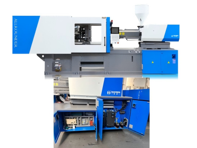
- Through-Holes: Forms holes by sealing between mold halves (e.g., hinge pins, bolt holes).
- Example: A box with integrated door hinges molded via shut-offs between the A/B mold faces.
- Undercuts & Snap-Fits: Creates retention features (e.g., clips) without side actions.
- Complex Geometry: Enables long channels or segmented cavities in wide parts.
Pros & Limitations
- Advantages:
- Cost Savings: Fewer mold components (sliders, ejectors).
- Faster Cycles: Eliminates post-machining.
- Precision: Reduces defects like weld lines or sink marks via controlled filling.
- Limitations:
- Design Sensitivity: Requires precise shut-off alignment to avoid leaks or mold damage.
- Material Constraints: High-viscosity or filled resins may need higher clamp pressure.
Emergency Stop injection molding machine Comparison to Alternatives
- vs. Side Cores: Lower cost but limited to shallow undercuts.
- vs. Kiss-Offs: Shut-offs focus on flow control; kiss-offs hide parting lines for aesthetics.
Real-World Examples
- Hinges: Molded axle holes for box lids without secondary drilling.
- Medical Devices: Flash-free fluid ports in syringes or connectors.
In summary, shutoff injection molding balances cost, efficiency, and precision by using smart mold design to form functional features directly. It’s widely used in automotive, electronics, and consumer goods for complex, high-quality parts.
How does the hydraulic emergency stop of an injection molding machine work?
The hydraulic emergency stop system of an injection molding machine ensures rapid response and safe shutdown during emergencies through a multi-layered interlocking mechanism. Here’s a detailed explanation of how it works:
- Emergency Stop Button Activation
- Hydraulic System Pressure Release
- Euromap Interface Integration
- Safety Circuits & Redundancy
- Reset & Restart Procedure
Emergency Stop Button Activation
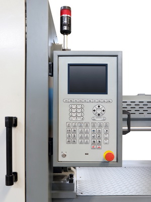
- Red Emergency Stop Buttons are installed on the control panel of the injection molding machine and associated equipment (e.g., servo-driven robots or handheld controllers). Pressing the button:
- Instantly cuts off the main power supply or hydraulic system power.
- Halts all moving components (e.g., mold clamping, injection actions).
- Certain peripheral devices (e.g., clamps, vacuum valves) may remain operational to prevent material spillage or workpiece damage.
Hydraulic System Pressure Release
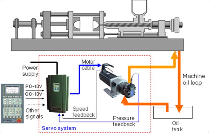
- The emergency stop triggers safety valves to shut off hydraulic oil flow, stopping hydraulic cylinders and releasing pressure. This prevents unintended mold closure or hydraulic motor overload.
- Example: Systems like NAIAD DYNAMICS use hydraulic emergency stops to instantly shut down system pressure during emergencies such as fire or pipeline rupture.
Euromap Interface Integration
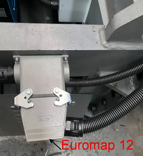
- Injection molding machines and robots communicate via standardized interfaces (Euromap12/Euromap67).
- Activating an emergency stop on either device triggers a synchronized shutdown of all connected equipment (e.g., conveyors, vacuum pumps).
- Note: Under Euromap67, the molding machine may not automatically stop during a robot’s protective stop, requiring additional safety devices (e.g., safety light curtains) for full protection.
Safety Circuits & Redundancy
- Safety Relays: Monitor the emergency stop circuit to ensure the machine cannot restart automatically after an emergency stop. Faults in the circuit trigger a power cutoff.
- Dual-Channel Circuits: Redundant emergency stop circuits (e.g., ZA1-ZC1 and ZA2-ZC2) interrupt robot power via the machine’s emergency stop switch.
- Safety Door Interlocks: Opening the safety door halts mold movements and triggers automatic mold opening to protect operators.
Reset & Restart Procedure
- After an emergency stop:
- Rotate the emergency button clockwise to reset.
- Diagnose the root cause (e.g., check hydraulic oil levels, temperature, pressure).
- Restart the system in manual mode for functional testing before resuming production.
Key Considerations & Challenges Emergency Stop injection molding machine
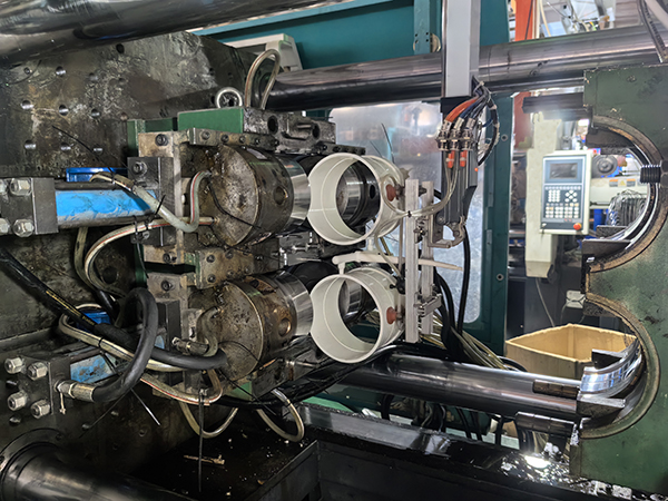
- Third-Party Equipment: Some devices connected via control cabinets may only stop the robot, not the molding machine, requiring compatibility checks and supplementary safeguards (e.g., safety light curtains).
- Euromap67 Compatibility: Adapters must meet safety standards (e.g., PL ratings) to avoid signal transmission failures.
- Maintenance: Regular testing of hydraulic components, valves, and safety circuits is critical to ensure reliability.
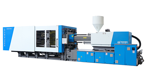
The hydraulic emergency stop system combines electrical-hydraulic interlocking, standardized interfaces, and redundant safety designs to achieve rapid shutdown and risk isolation. However, system reliability depends on regular maintenance, compatibility validation, and adherence to safety protocols.