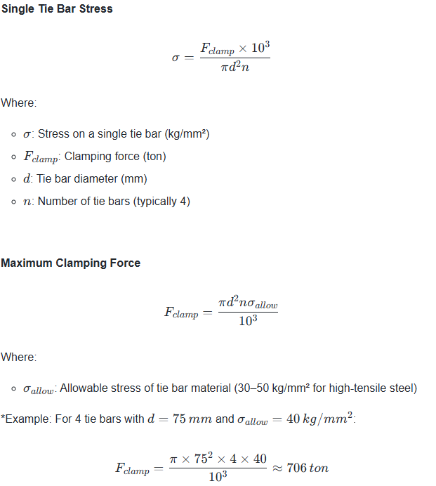
The calculation formula of figure tonnage from tie bar stretch is as follows:
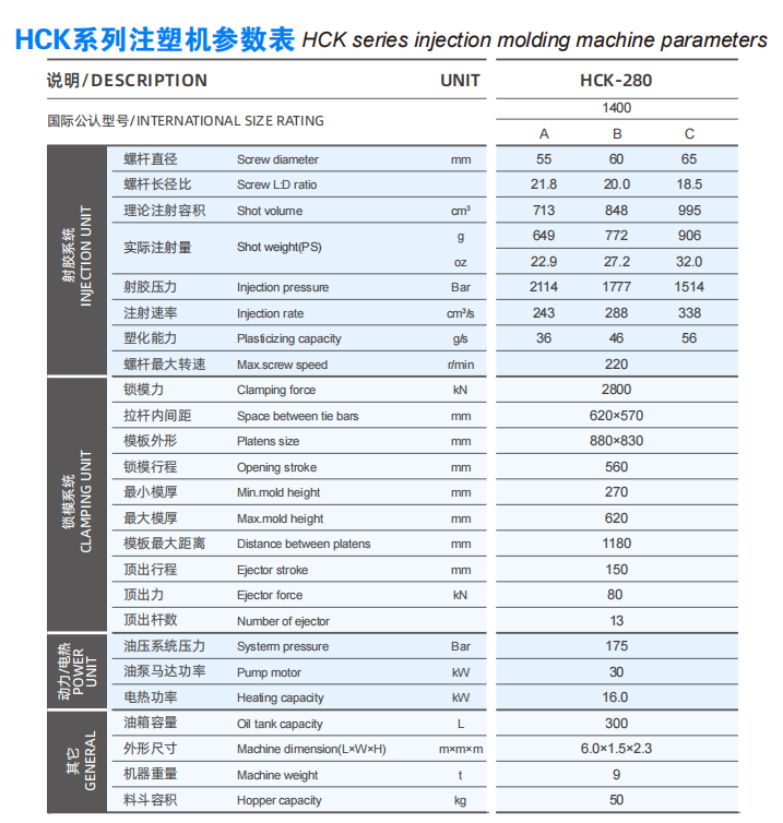
The parameters such as the pull rod diameter and mold opening stroke of injection molding machines of different tonnages are all different.
Under normal circumstances, as the tonnage of the injection molding machine increases, the diameter of the pull rod and the mold opening stroke also increase.
For example, the pull rod diameter of a 90-ton injection molding machine is 60 millimeters, and the mold opening stroke is 320 millimeters.
The diameter of the 650-ton tie rod has been increased to 150 millimeters, and the mold opening stroke is 880 millimeters.
This indicates that the larger the tonnage, the longer the stroke of the pull rod is usually.
This is because larger molds require a longer stroke to open the mold.
Injection Molding Machine Tonnage
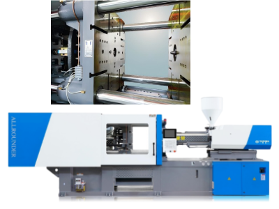
The tonnage of an injection molding machine usually refers to its maximum clamping force, which is the maximum pressure it can withstand.
Tonnage is an important parameter to measure the performance and capability of an injection molding machine, and is usually expressed in tons.
For example, a 100-ton injection molding machine can withstand a maximum clamping force of 100 tons.
The larger the tonnage, the larger the plastic products that the injection molding machine can make.
The key factors for calculating tonnage
- Tie bar stretch
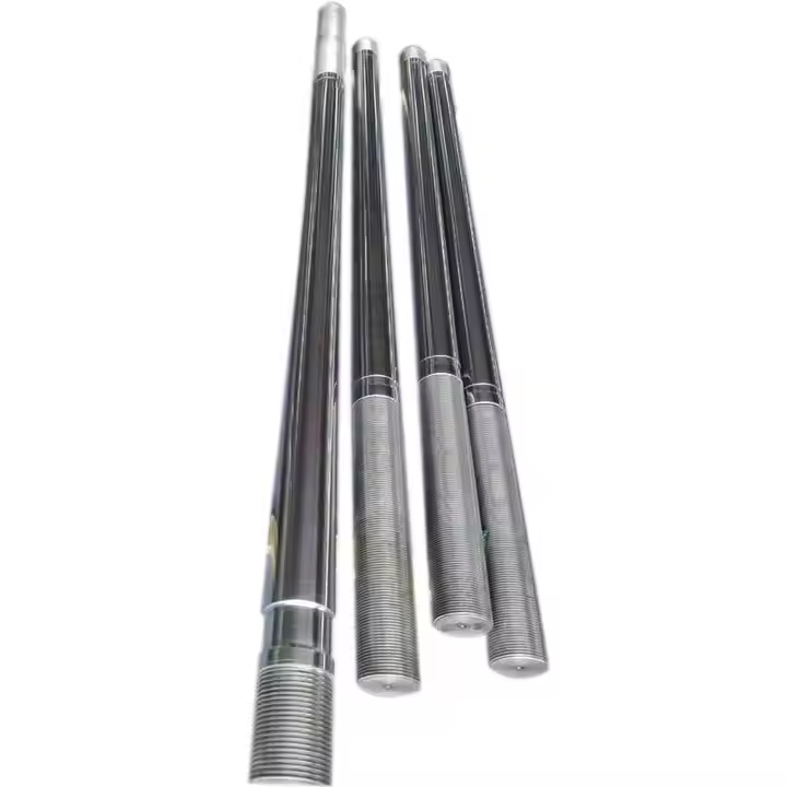
- Tie-bar
Tie bar stretch
Tie bar stretch calculate tonnage, you need to consider the material properties, diameter, length, and tension applied to the tie bar.
In injection molding systems, tie rods serve as critical structural components that apply clamping pressure to secure the mold.
During operation, these massive rods generate clamping tonnage through tensile stress when operators properly tension them.
To maintain optimal performance, technicians must ensure even stretching across all four rods.
As this uniformity directly determines the distribution of clamping force on the mold surface.
Therefore, the tonnage of the injection molding machine determines the maximum clamping force it can withstand.
And the tie rod is the key structural component to achieve this clamping force.
Choosing the right tie rod spacing and tonnage is essential to ensure the proper operation of the injection molding machine and the production of high-quality products.
Tie-bar
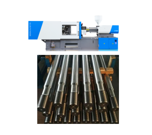
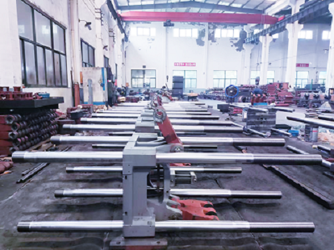
The tie bar primarily serves as a key component that holds the mould and transmits the clamping force.
Typically, injection molding machines utilize four tie rods to equally distribute the clamping force.
Furthermore, by utilizing the formula σ = F/A (where σ is stress, F is force, and A is cross-sectional area), engineers can calculate the stress on each tie bar.
Thereby ensuring structural stability during high-pressure operations.
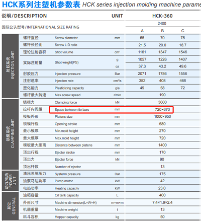
The tie-bar spacing refers to the horizontal and vertical inward spacing of the tie-bars, and different types of injection molding machines have different tie-bar spacing.
Calculating tonnage
- Determine the type of tie rod and working conditions
- Calculation of axial force
- Calculate stress
- Consider the safety factor
- Consider the material properties
- Check the calculation results
Determine the type of tie rod and working conditions
The first step is to determine the type of tie rod to be used (e.g., manual tie rod, hydraulic tie rod, etc.) and the working conditions (e.g., shaft diameter for tension/thrust work, etc.).
For example, for manual tie rods, the pressure screw diameter should be at least half the diameter of the shaft on which the tension/thrust is working.
For hydraulic tie rods, the maximum tonnage should be 8 to 10 times the value of the shaft diameter (inches) to be stretched or pushed.
Calculation of axial force
According to the working conditions of the tie rod, calculate the required axial force.
The axial force FN can be calculated by a formula in the mechanics of materials, e.g., FN=F=40kN.
Calculate stress
The stress σ can be calculated by the formula σ=FN/S, where S is the cross-sectional area.
For example, if the axial force FN=40kN and the cross-sectional area S=2bh=21428=896mm² are known, the stress σ=40000/896≈44.64MPa.
Consider the safety factor
In practical applications, the safety factor needs to be considered to ensure the safety of the structure.
For example, if the strength safety factor is 1.5-1.8, the allowable stress should be less than the yield limit of the material divided by the safety factor.
Consider the material properties
The hardness and modulus of elasticity of the material also affect the tonnage of the tie bar stretch.
For example, the harder the material, the higher the tension force required.
Check the calculation results
Finally, engineers must check the calculation results to verify compliance with strength conditions and safety requirements.
For instance, they can apply finite element analysis to evaluate stress distribution and deformation during tie bar stretching.
By following these steps and utilizing the derived formulas, the methodology enables accurate calculation of tie rod tonnage under tensile conditions.
However, it is critical to emphasize that practical applications require additional considerations.
Particularly regarding the effects of friction and temperature fluctuations on tie rod performance.
Effect of tie bar stretch on tonnage
- The relationship between tonnage and tie rod spacing
- The synergistic effect of the pull rod stroke and tonnage
The relationship between tonnage and tie rod spacing
The spacing of the pull rods is one of the important factors affecting the installation of the mold.
A larger tie rod spacing can accommodate larger molds, and the increase in tonnage means a stronger clamping force.
To ensure that the mold does not crack due to insufficient pressure during the injection molding process.
Therefore, an increase in tonnage is usually accompanied by an increase in the spacing of the pull rods to meet the requirements of larger molds.
The synergistic effect of the pull rod stroke and tonnage
In practical applications, the stroke of the pull rod and the tonnage need to work in coordination to ensure the stability of the injection molding process and product quality.
For instance, large-tonnage injection molding machines are typically equipped with longer pull rod strokes to accommodate large molds and complex product structures.
At the same time, the adjustment of the pull rod stroke also needs to take into account the influence of tonnage.
To ensure that the mold will not be damaged due to insufficient stroke during the mold opening and closing process.
How Haichen optimizes tie bar stretch
In order to optimize the support structure of the tie rod of the injection molding machine to improve its durability, Haichen has taken the following measures:
- Improve the clamping structure
- Use of high-rigidity formwork structures
- Improve the guide rod support device
Improve the clamping structure
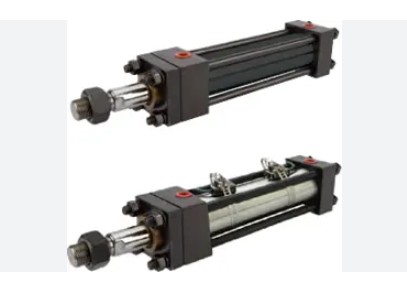
Haichen intelligent injection molding machine adopts the clamping structure of the high-pressure clamping cylinder fixed in the moving platen.
And the tie rod passes through the piston rod of the high-pressure clamping cylinder.
And no longer acts as the function of the piston rod of the high-pressure clamping cylinder.
Which solves the problem that the floating tie rod affects the sealing effect of the high-pressure clamping cylinder.
In addition, the moving platen movement adopts frame support and tie rod guide design.
Which makes the tie rod not easy to break and the clamping structure has a longer life.
Use of high-rigidity formwork structures
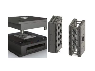
Finite element analysis of the formwork of the injection molding machine is carried out by large-scale engineering analysis software to identify weak points where cracks may occur.
Then, Haichen will redesign the shape and position of the formwork ribs to strengthen the rigidity of the formwork and avoid stress concentration.
Improve the guide rod support device
The design implements a guide rod support device with high stability.
Furthermore, the arc design significantly reduces the probability of guide rod bearing deformation.
Additionally, reinforcing the plate on the support base plate combined with the arch structure effectively shares the force distribution.
In addition, the threaded fixing column and locking head ensure the stable support of the support for the guide rod.