Position Adjustment of the Pouring Gate
To adjust the pouring gate position, follow the steps below, considering a 60mm distance between the central position of the hot chamber die casting machine and its drooping central position. It is necessary to place six special cushions with a height of 60mm under the tilted guiding rail to determine the drooping central position.
The procedures are as follows:
Release the two bolts on the piston rod of the tension oil cylinder and disconnect the fixed platen from the piston rod.
Remove the six set bolts from the tilted guiding rail.
Slowly raise the tilted guiding rail using the manual commutation valve DV10.
Install the six special cushions in their designated positions.
Reverse the operation of the manual commutation valve DV10 to gradually lower the tilted guiding rail.
Replace the M16×50 bolts with M16×110 bolts and securely fix the tilted guiding rail.
Tighten the two bolts on the piston rod of the tension oil cylinder for added reinforcement.
Note: after adjustment, adjust the manual commutation value DV10 in the middle Way.
Installation of die-casting mould
Operation sequence:
Set the selector switch SA5 to the “MANU” position.
Press the “DIE OPEN” button SB3 or use both hands to press the die close buttons SB1 and SB2. After completing all the necessary preparations, set the machine to a die-close state.
Inside the control box, turn the mold-adjustment changeover switch to the “ON” position. Then, press the corresponding “DIE THICK” button and “DIE THIN” button to adjust the distance between the moving platen and the fixed platen slightly greater than the mold thickness. Proceed with the die opening.
Remove the position sleeve and gasket to allow the nozzle to protrude and align with the mold (refer to details in the 10.3 drawing).
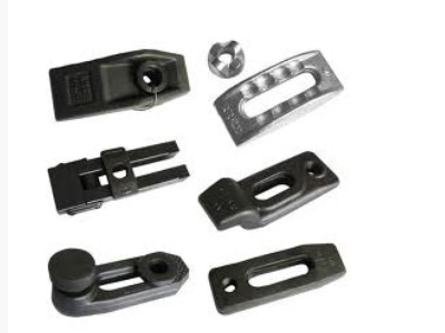
Install the mold on the fixed platen, ensuring that the mold cast gate case is correctly aligned with the nozzle. Secure the mold in place using bolts.
Install the ejector rod into the guiding hole of the moving platen.
Slowly close the mold.
Activate the drive mechanism to bring the moving platen closer to the mold, and then secure the moving platen with bolts.
If necessary for the ejector plate to perform a pullback action, install the pulling back bar.
Perform the die opening.
Adjust the drive transmission mechanism to slightly rotate the tie bar nut to the required degree. This will generate the appropriate die-locking force. Once the die locking force has been correctly adjusted, change the mold-adjustment changeover switch, which is under operation, to the “OFF” position.
Install the position sleeve and gasket (refer to details in the 10.3 drawings).
Repeat the die opening and closing actions several times to check the adequacy of the pretension. When the correct die locking force has been achieved through machine adjustment, rotate the toggle connecting rod to the endpoint, and position the piston rod of the die-closing cylinder to the endpoint, activating the travel switch of the matched die.
After adjusting the die locking force, select the quick die-close state from the human-machine interface frame.
Note: once the phenomenon of adjusting mold out of control appears,pleasepresstheemergencybutton, and check the cause, after the failure has been fixed, then start up the pump again.
Adjusting the distance between the nozzle and the die-casting mould after disconnecting
When closing the mold, under the action of the tension cylinder, the nozzle, and the mold are closed, the tension stroke switch is adjusted to close the switch appropriately, and the nozzle is unhooked after injection so that the distance between the nozzle and the mold is 1~5mm. (Adjusting the nozzle closing delay time can control the unhooking distance. If the time is set to zero, the nozzle will not be unhooked)
With the passage of time and frequent use, the injection head may lose its original accuracy. Therefore, it is necessary to regularly disassemble the nozzle and modify it on a grinder or lathe.
When the repaired length has exceeded the stretching stroke, the injection head should be replaced. This is because the piston in the cylinder moves to the bottom of the cylinder due to stretching, and the injection nozzle cannot be sealed.
When designing a die-casting mold, special attention should be paid to its safety and reliability, and relevant technical specifications should be strictly followed to determine the installation position and size of the mold. Calculate the thickness of all die-casting molds, check the maximum and minimum pressing thickness of die-casting, determine the size of the ejector device and other devices, determine the position and size of the ejector rod and return rod, and check the ejector stroke distance and pre-reset device size. During the production process, we should avoid situations such as multiple castings sticking to each other, castings getting stuck on the ejector rod, casting pouring head cracking, and some castings still getting stuck in the die casting mold, so as to prevent accidents and ensure the safety of operators. The two sets of die casting molds should be firmly installed on the movable mold frame and the fixed mold frame.
Dismount of goose neck kettle
Operation procedures are as follows:
1)Dismount injection piston;
2)Retract the die-closing unit;
3)Dismounttheheatingunitoninjectionnozzle;
4)Dismount the heating block;
5)Disassembly injection nozzle(Also disassembly with gooseneck kettle);
6)Loose two baffle plate bolts and dismount baffle plate;
7)The gooseneck kettle is equipped with a set of Lewis holes, which are used for lifting and disassembling the gooseneck kettle.
Method of dismounting the damaged injection piston which has been got stuck
Operation procedures are as follows:
Ensure that the zinc alloy is in a molten state;
Initiate the injection return process and set the returning force to its maximum level;
Place a cushion with the appropriate thickness on the gooseneck kettle. use the special bar to knock out and make the piston ascend and unload the piston, causing it to ascend and unload from the injection chamber. This will complete the removal of the piston from the inner hole;
Replace the piston ring with a new one.