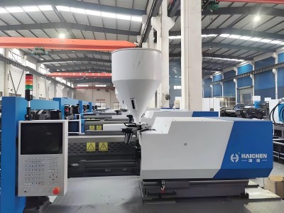
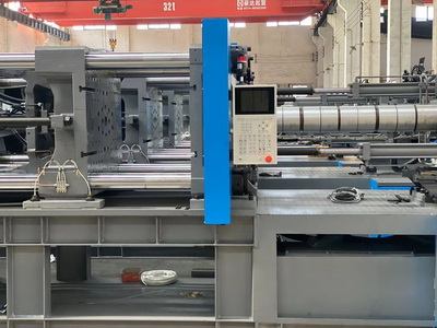
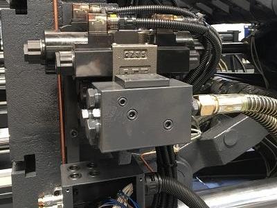
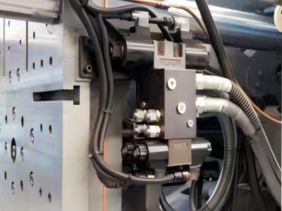
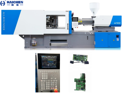
Injection molding machine spare parts including mechanical components, hydraulic systems, electrical components, heating and temperature control systems, and mold-related components.
China is one of the most important countries in plastic injection molding machines, the annual total production ranks first in the world in recent years.
Ningbo, Hangzhou, and Guangzhou these three cities produce 70-80%of the injection molding machines in China.
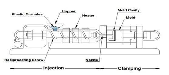
Injection molding machine Spare parts–Nozzle
The nozzle is one of the injection molding machine’s spare parts and plays an important part in the injection molding machine.
In order to ensure the normal progress of the injection process, the barrel, screw, and nozzle may need to be adjusted after replacing the mold.
When making these adjustments, the machine must be heated to the appropriate temperature.
And the barrel and screw should be cleaned with appropriate materials if necessary.
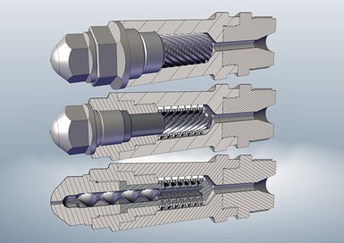
Nozzle Centering Adjustment
The nozzle center needs to be readjusted after machine debugging, frame leveling, or barrel replacement.
When the mold comes into contact, the nozzle may move up, down, or sideways and must be readjusted.
The maximum deviation between the nozzle center and the positioning ring should not exceed 0.2mm.
Note
When measuring the center of the nozzle, the barrel temperature should be heated to at least 200 degrees.
And the nozzle should be moved to the level of the mold surface.
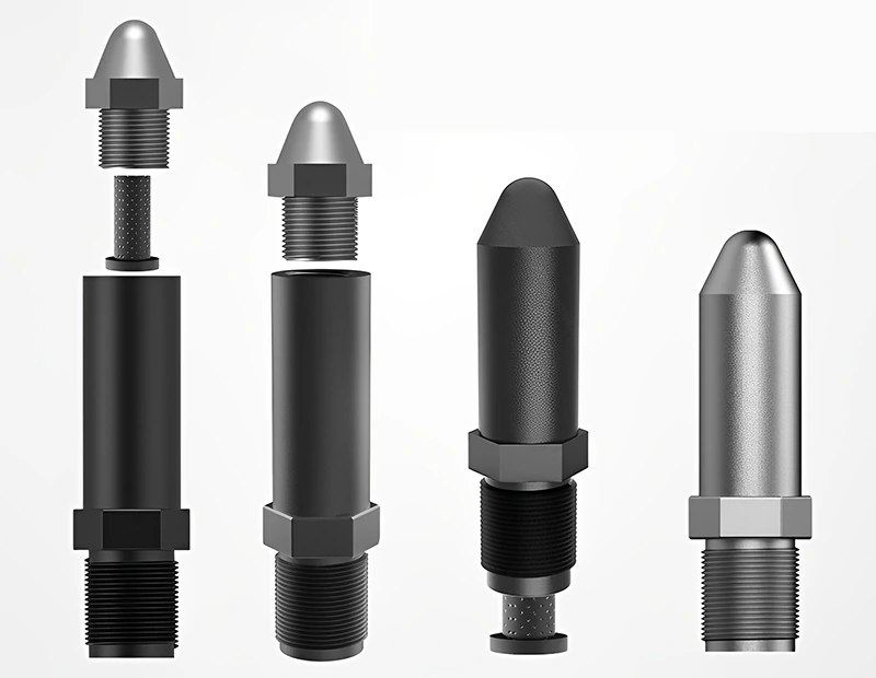
Nozzle center adjustment steps
Place the level horizontally and vertically on the injection rail.
- After the mold is installed, continuously press [ADVANCE] of the nozzle button to make the nozzle tip contact the mold to check the nozzle misalignment.
- At this time, insert a piece of paper between the nozzle head and the mold to alleviate directional misalignment.
- Press [RETRACT] of the nozzle button to move the nozzle to the retract limit.
- If the center of the nozzle moves vertically, loosen the clamping bolt that secures the injection unit to the base.
- Adjust the height of the injection unit with the adjustment bolt and ensure vertical alignment.
- If the center of the nozzle moves further horizontally, please use the horizontal adjustment bolt provided on the operation to adjust the horizontal position of the injection device.
- After adjustment, tighten the clamping bolts.
- Make the nozzle tip contact the mold and check the misalignment again.
Conclusion
Proper nozzle center adjustment is critical to maintaining the accuracy and efficiency of the injection molding process.
Remember to adhere to specified temperature requirements and perform regular maintenance for optimal performance.
Injection molding machine Spare parts–Mould
Mold installation
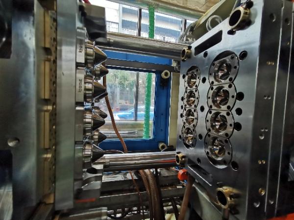
1) Preparation
Before installing the mold, a machine must be selected that is sized appropriately for the specific mold being installed.
After selecting the machine, it must be inspected to determine its status.
Once the machine inspection is completed, the mold can be installed.
2)Check
Make sure the mold is installed with connecting straps.
This strap should connect the two halves of the mold and prevent them from separating during shipping.
3) Positioning
Use the chain drop device to lower the mold from the top of the machine.
At this time, the mold must be slightly raised and lowered to try to position it.
So that the positioning ring on the mold slides into the positioning hole on the pressure plate.
The top of the mold should be slightly tilted when attaching the chain.
4) Fixing
The tilted mold should be placed slightly above the positioning hole of the fixed pressure plate.
And close to the pressure plate when the mold slowly descends.
When the mold is gently lowered, the positioning ring will automatically slide into the template’s positioning hole.
5) Verify Alignment
Check the alignment of the mold by visually inspecting the position of the mold relative to the platen and injection unit.
Make sure the mold is parallel and centered within the machine to avoid any misalignment issues during operation.
6) Final inspection
Remove the chain hooks, eye bolts, and connecting straps from the mold.
Recheck each clip on both halves to make sure they are tight.
Start the machine and slowly open the clamps at low pressure, watching for any signs of the mold halves becoming stuck or sticking together.
Open the mold about 1/2 way and stop.
Shut down the machine and inspect the mold thoroughly to make sure it is installed correctly.
7) Post-installation inspection
Start the machine and continue to open the mold slowly, then stop the mold in the fully open position as described.
Adjust settings to ensure correct ejection.
Lubricate all moving parts such as ejector rails, guide pins, and slides.
Wipe off any excess.
Clean the cavity surface gently.
Close the mold and turn off the machine.
Mold debugging
After the molding mold is moved and the template is installed and fixed, an idling test, debugging, and inspection must be carried out.
To ensure that the mold closing movement on the two halves of the mold template is coordinated with the action of the mold closing mechanism.
In order to ensure smooth progress of injection molding production and avoid mold malfunctions or they are damaged.
1) Check the sliding fit
Check the sliding fit of the guide pillar and guide bush on the mold to see if it can be guided normally when the mold is opened and closed.
There should be no mold-locking interference in the sliding fit of the two parts.
2) Low voltage, slow closing method.
Check whether the working process of the two halves is accurate, and the connection between the two parts should be tight.
3)Pay attention to the even tightening force of each nut
If the two halves of the mold are properly combined, tighten the locking nut again.
4) Open the mold slowly.
Adjust the working position of the ejector rod.
So that the period between the mold ejector plate and the fixed template is not less than 5 mm.
The ejector rod can work normally and prevent damage to the mold.
5)Ejector rod
When the ejection or mold opening force realizes the core pulling action of the mold, attention should be paid to the coordinated movement of the ejector rod.
And the core pulling distance should ensure the safety and accuracy of the two mechanisms.
And prevent mutual interference, hindering work or Damaged molds will not work.
6) Adjust the distance of the movable template to adjust the control switch of the fixed stroke.
7) Adjust and test the clamping force.
The adjustment of the clamping force should start from a low value, and the stretching action of the elbow connecting rod should be more flexible and easy.
According to the process conditions, whether there is a certain temperature during the molding process.
For injection molded products, the debugging of the clamping force should be carried out after the specific temperature of the mold rises to the process temperature.
8) After all parts of the mold and die are adjusted, the sliding fitting parts should be properly filled with lubricating oil.
9)Auxiliary accessories
Equipped with auxiliary accessories such as electric heating elements, control instruments.
And hydraulic, pneumatic, and cooling circulating water pipeline installation.
Then perform debugging to check the accuracy of resistance heating and instrument control.
Hydraulic and pneumatic pressure testing and test reliability; check whether there is leakage at each pipe connection.
10) Mold debugging, mold, and die force adjustment are completed, and the debugging test begins.
Injection molded plastic products are reasonable and have no flash and minimum clamping force.
A large clamping force will easily deform the mold and accelerate the wear of various parts within the mold.
A more appropriate mold closing force (clamping force) can also save energy consumption.
Rapid Decomposition of Plastics
Guidelines
Especially poly toluene and PVC, can decompose and explode when heated for prolonged periods.
To prevent accidents, these guidelines should be followed process plastics strictly in accordance with their material properties and processing parameters, especially the processing temperature and the residual time in the plasticizing barrel.
When handling heat-sensitive materials, minimize the residence time of the material in the barrel.
Clean the barrel
Clean the barrel that has been used for heat-sensitive materials with polyethylene before production interruption or material denaturation.
Afterward, cease heating,melting temperature of injection molding plastics
When plastic injection molding, choosing the correct melting temperature is very important for product quality.
In general, the allowable melting temperature error of injection molded plastics is stricter than that of molded amorphous resins.
And the temperature conditions directly affect the final quality of the product.
Plastic types
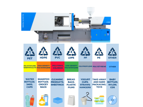
Commonly used plastic types, such as PP, PE, PC, and PET (polyester), have different melting temperatures and injection molding temperatures.
Problems caused by the wrong melting temperature.
Molding problems
The melting temperature is not allowed to be too high or too low during injection molding of engineering plastics.
The correct melting temperature of engineering plastics should be within the melting temperature distribution range of the material.
Too high a temperature can degrade or decompose plastics, breaking the bonds of polymer polymers.
While additives such as pigments, impact resistants, etc. in the melt will also decompose together.
As a result, the physical and mechanical properties of the product are reduced.
And various obvious defects (due to product decomposition) and unpleasant odors appear in the appearance.
Quality issues
When the temperature is too low, the material can not achieve sufficient melting.
And the plastic cannot complete the homogeneity required by molding.
Which seriously reduces the impact strength of the product and leads to the reduction of other physical properties of the product.
In addition to the melting temperature, the residence time of the polymer in the barrel also plays an important role.
Which is normally between 2 and 9 minutes.
If the dwell time is extended, thermal decomposition may occur, even if the melting temperature is set correctly.
If the dwell time is too short, the melt usually does not achieve complete homogeneity.
In order not to cause more serious accidents, the residence time of the material in the barrel should be minimized when handling heat-sensitive materials.
Before production interruption or material denaturation, clean the barrel used for heat-sensitive materials with polyethylene.
Injection molding machine Spare parts–screw
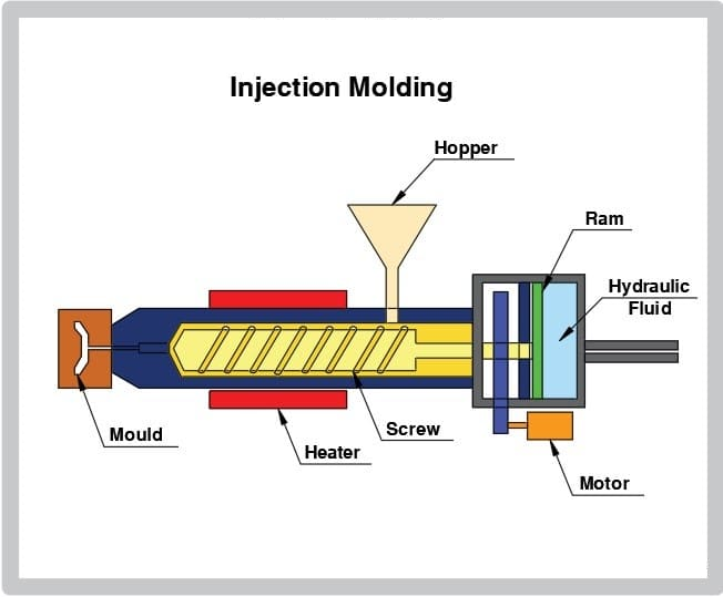
The screw is one of the most important injection molding machine spare parts.
Its main function is transporting, compacting, melting, stirring, and pressuring the plastic.
These operations are completed by the rotation of the screw in the barrel.
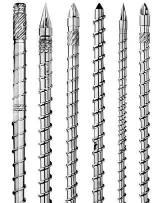
The screw is usually divided into three sections
Feeding section, compression section, and homogenization section.
In practical applications, it is very important to choose the right screw type.
Different types of screws are suitable for different plastic properties and processing requirements.
Screws and barrels are important molding machine parts in plastics processing machinery, including injection molding machines and extruders.
As well as in the food processing industry.
They are responsible for melting, mixing, and stirring the raw material and then shaping it into the desired product.
Now let’s see how to disassemble the screw barrel.
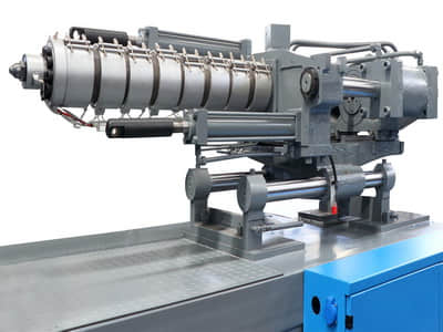
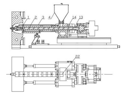
1.Return the injection unit to the right final position (mechanical stop).
2.Remove the hopper and clean the screw barrel1 manually.
3.Turn off screw barrel heating and cooling. Disconnect the heating ring connection
plug, thermocouple and cooling water hose connector.
4.Remove the barrel guard 2.
5.Move the screw all the way to the front(manual operation).
6.Loosen the front barrel retaining screw. Remove the nozzle and front barrel.
Notice 1
There is a risk of fire if the screw barrel is not completely cooled. Wear protective gloves and glasses!
Be careful with scraps when cleaning- the plastic is hot!
Loosen the set screw and remove the barrel nut14
Loosen the screw half ring
Move the injection piston backward until the screw is disengaged from the coupling (manual: operation).
Notice 2
Even with the heating turned off or insulated, there is a high voltage to ground at the heating cartridge, heating coil, etc.
The air isolating switch (main power switch) must always be open when repairing the heating system.
Screw removal
1. Loosen the shooting cylinder1, and manually turn the shooting table base
2. Place a wooden block between the screw and the back of the shooting seat, move the shooting table forward manually (low speed).
Push the screw out of the barrel, and push the screw horizontally.
The screw is removed from the machine.
Barrel disassembly
1. Remove the loading platform and loosen the set screw to remove the barrel nut and screw half-ring.
2. Make sure the harness is in the shackle.
3. Lift the cartridge straight up and out of the machine.
Above is how to disassemble the screw barrel.
Haichen will give you professional answers, if you have any questions, please come to consult us.
Other injection molding machine spare parts
There are some injection molding machine spare parts such as screw barrels, which may change after six months.
These spare parts are used to replace worn or damaged parts in the machine.
Advantages of injection molding machine spare parts for original.
Original spare parts for longer machine service life.
Uncomplicated ordering and immediate delivery.
Some examples of injection molding machines’ spare parts include:
Screw barrel
Nozzle
Hydraulic components
Electrical components
We will introduce the screw barrel in detail.
Screw barrel
The screw barrel is an important component of the injection molding machine. Its role is to convey, compact, melt, stir, and pressure the plastic.
All of these procedures are done by the rotation of the screw inside the barrel.
When the screw rotates, the plastic will have friction and mutual movement on the inner wall of the barrel.
The bottom surface of the screw groove, the propulsion surface of the screw edge, and between the plastic and the plastic.
And the forward propulsion of the plastic is the result of this combination of movements.
And the heat generated by the friction is also absorbed and used to increase the temperature of the plastic to melt the plastic.
The structure of the screw barrel will have a direct impact on the extent of these effects.
To improve the plasticizing quality, the screw can be designed as a split screw, a barrier screw, or a split-type screw.
Screw barrel diameter and tightening torque
The injection unit is available in three different diameter screw sizes.
The smallest diameter screw barrel has the smallest injection volume but the highest injection pressure.
The largest diameter screw barrel has the largest injection volume but the smallest.
Injection pressure
The length of the screw is generally not measured by absolute length but by its length relative to its diameter.
In this way, the length of the screws with different diameters can also be compared.
This length is called the length-to-diameter ratio and is represented by L/D.
Of course, the length of the screw is only counted as the part with threads.
A more accurate algorithm counts the hopper’s midline and calls it the effective length or effective length-to-diameter ratio.
An injection molding machine usually has three screws to choose from, called A, B.
And C screws, with small, medium (standard), and large diameters respectively.
They have an aspect ratio of around 22, 20, and 18.
Adjustment of the second board slider
Introduction
The two-plate sliding foot device is an auxiliary device used to support the moving template to ensure that the four tie rods are not bent.
If the device is adjusted too tightly, it will increase the load of mold adjustment, making it difficult to adjust the mold.
And if it is too loose, it will lose the function of protecting the bending of the tie rod.
This device has been adjusted to the best level before the machine leaves the factory, and it does not need to be adjusted for a new machine.
But after working for a period of time, it must be checked for looseness, and if it is loose, it must be adjusted.
Classification
The double-board sliding foot device is divided into planar drag boards and bevel drag boards
Planar drag board device
Gliding foot device for planar dragboard
Adjust the height of the sizing block under the machine body and correct the flatness of the machine.
Then remove the molds of the 2 boards for adjustment.
Loosen the locking nut and rotate the adjusting bolt (clockwise to bend the pull rod downward, counterclockwise to push the pull rod upward).
When adjusting the pull rod to the horizontal position, tighten it with the lock nut.
Bevel drag board device
Gliding foot device of bevel drag board
Loosen the left adjusting nut, and then rotate the right adjusting nut to move the lower carriage to the left.
Loosen the right adjusting nut, and then rotate the left adjusting nut to move the lower carriage to the right and bend the pull rod downward.
When adjusting the pull rod to the horizontal position, tighten the left and right adjusting nuts.
Adjustment of melt adhesive back pressure
Back pressure, also known as plasticizing pressure, can be controlled by adjusting the return throttle valve on the back of the injection cylinder.
When the melt is fed, the proportional back pressure valve controls the oil pressure of the injection cylinder to generate a certain screw back pressure to facilitate the discharge of gas in the material.
Backpressure settings typically start at 50 PSI and increase in 10 PSI increments.
The maximum hydraulic pressure of the equipment is usually 300 PSI.
Back pressure is too low
May be air-trapped Plasticization may not be good enough
There may be shrinkage, air bubbles, and cold material on the product’s surface.
There may be bubbles inside the product
The back pressure is too high
The melt pressure in the front section of the barrel is too high, which reduces the plasticizing efficiency.
For plastics with poor thermal stability (such as PVC, and POM), the increase in melt temperature may cause decomposition, or the degree of discoloration of the colorant may increase.
The screw retreat speed will be reduced, which may increase the charging time and total cycle time.
In the next cycle, the cold material may block the nozzle or the product may have cold spots.
May damage the nozzle heater
Increased wear of screw and barrel
Haichen Machinery
Haichen has rich experience in plastic injection molding production.
We are committed to providing fully automatic, excellent, and precise plastic injection molding machines.
That can provide you with efficient and large-volume product output needs.