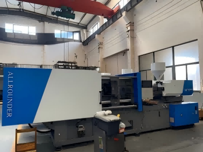
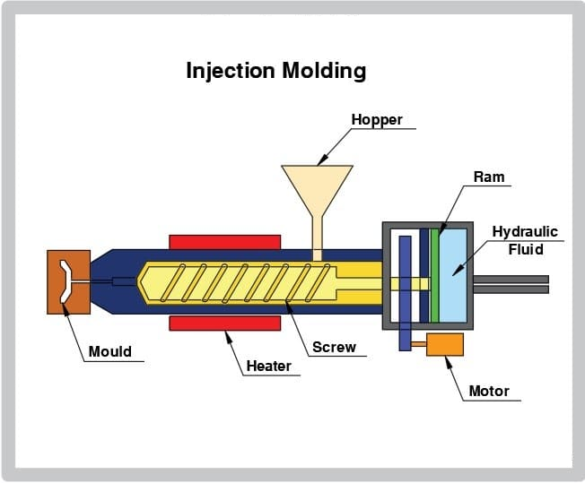
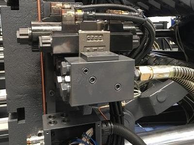
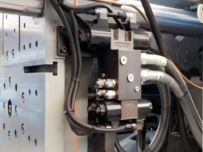
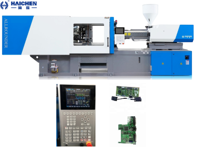
A hydraulic system in an injection molding machine work by using pressurized hydraulic fluid to generate the force needed for mold clamping and plastic injection, ensuring precise control and consistent part production.
A hydraulic system is the powerhouse behind every injection molding machine, providing the controlled force needed for the meticulous injection of molten plastic.
Without it, the high pressures and rapid, repeatable movements essential to filling the mold cavity would simply be impossible.
This article will therefore detail the workings of the hydraulic system within these machines and clarify how it fits into the wider molding operation.
Additionally, we will outline the advantages that hydraulic actuation brings, illustrating how these advantages translate into greater efficiency and dependability for contemporary molding plants.
Basic Components of a Hydraulic System
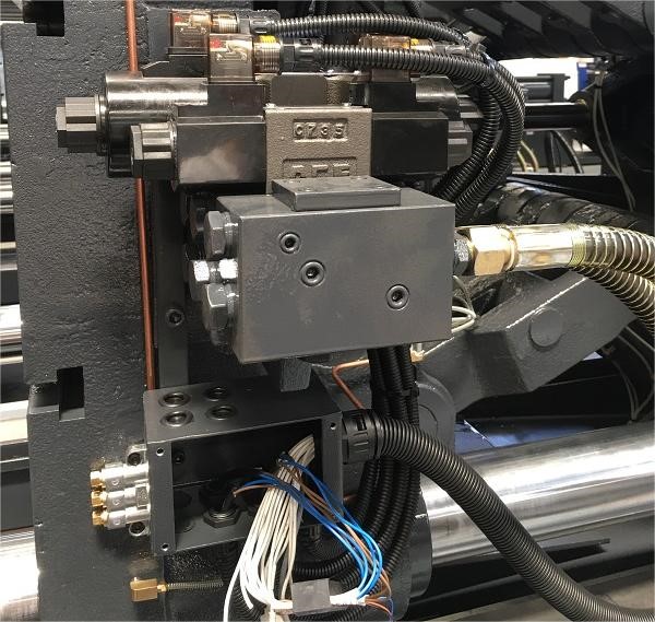
The hydraulic system in an injection molding machine consists of several key components that work together to generate and control fluid power. These components include:
- Hydraulic Pump: This is the heart of the system, responsible for generating the flow of hydraulic fluid under pressure. The pump converts mechanical energy from an electric motor into hydraulic energy to drive the machine’s actuators.
- Reservoir: The reservoir stores the hydraulic fluid and provides a place for air to separate from the fluid. It also helps in cooling the fluid and maintaining a stable supply.
- Valves:Various valves, such as directional control valves and pressure relief valves, control the flow and pressure of the hydraulic fluid. They ensure the fluid is directed to the right components at the right time.
- Actuators:These are the components that convert hydraulic energy back into mechanical energy. In an injection molding machine, actuators drive the mold clamping unit, the injection unit, and other moving parts.
The Working Principle
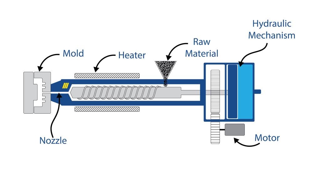
The hydraulic system in an injection-molding machine is based on the straightforward idea that liquid transmits force exactly the same in all directions. Here is how it carries out the injection process step by step:
- Fluid Pressurization: The hydraulic pump lifts fluid from the main reservoir and compresses it. Lines and fitted valves route the now-pressurized liquid to the cylinders and motors that form the machine’s motions.
- Control and Distribution: A bank of directional valves sends the liquid to the right cylinder or motor in the sequence the operation calls for. When it is time to hold the two halves of the mold the valves channel flow to clamps that pull the two plates tightly together.
- Mechanical Movement: The fluid now at pressure proceeds into the designated actuator. It then translates hydraulic force into mechanical movement. In the injection unit specifically the liquid forces either a plunger or a rotating screw to ram molten plastic into the mold cavity.
- Pressure Regulation: To keep the entire system safe and steady pressure-relief valves monitor for pressure spikes. The valves crack open and vent excess upstream liquid back to the reservoir preventing damage avoiding surges and maintaining a steady, repeatable operation.
Benefits of Hydraulic Systems in Injection Molding
Advantages of Hydraulic Systems in Injection Molding Hydraulic circuitry continues to be a key enabling technology in modern injection molding, offering a suite of competitive benefits:
- High Force and Accuracy
- Energy Efficiency
- Availability and Longevity
- Modularity
High Force and Accuracy
Capable of generating considerable tonnage, hydraulic systems are ideally suited to accommodate large mold cores. And high-volume part geometries, sustaining peak forces with micro-second response times. The carefully engineered feedback loops maintain sub-millimeter repeatability in both injection and clamping stages, delivering tight part tolerance and minimizing scrap rates.
Energy Efficiency
Modern hydraulic designs have drastically minimized energy consumption. Cooling stops, pre-charge volumes, and adjustable-displacement actuators harness load surges, permitting energy commands to trail commanded stroke far more closely. Overall energy expenditure drops 40% to 60%—a savings yield no slower cycle or slightly cooler hydraulic fluids.
Availability and Longevity
Hydraulic circuits have retained their reliability edge against rival actuators. High-toughness fluid seals, heavy-duty heat exchangers. And custom thermal isolators stand up to continuous operation in the fiercest hot, oily, and vibrating environments. Sensors measure fluid viscosity, bacteria, and Luoi infl to feed algorithms that extend service life to three times, and to route the shop service tech before an unceremonious stop.
Modularity
Tool bases that range from horizontal-profile swing to three-plate orbital designs yield readily to reconfiguration. Swivel servovalves, color-coded quick-disconnects. And pre-tested integrated manifolds drastically shorten re-tooling lead-time. Within compact cabinets, pre-loaded PLC libraries exploit integrated motion to realize ballistic injection and logically balanced cooling, establishing hydraulic circuitry. As the go-to logic and drive tier in the most congested injection-variable projects.
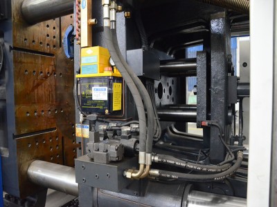
In summary, the hydraulic power unit is not merely a component; it is the controlling heart of the injection molding process, translating stored energy into the fine motions. And intense squeezing needed to produce flawless plastic parts, production after production. By understanding how these systems work and optimizing their performance, manufacturers can achieve high-quality parts and efficient production processes.