A limit switch in injection molding is a critical mechanical and electrical control component used to ensure the safety and precision of the mould during operation.
Its malfunction often causes the entire injection moulding machine to behave erratically and transmit abnormal signals.
The primary function of a limit switch is to verify the correct position of critical components within the injection mould, ensuring that the mould can safely close or open. For example, after injection moulding is complete, the limit switch can confirm whether the ejector plate has fully retracted, allowing the mould to close and preventing mould damage caused by the ejector plate not fully retracting.
Additionally, the limit switch can be used to control the retraction position of the screw, ensuring the accurate amount of molten material is injected each time.
To determine whether a limit switch in an injection molding machine is damaged, follow these steps combining visual inspection, functional testing, and electrical diagnostics:
- Visual Inspection & Physical Condition
- Functional Testing
- Electrical Diagnostics
- Lifespan & Environmental Factors
- Replacement & Maintenance Tips
- Common Failure Scenarios
Visual Inspection & Physical Condition
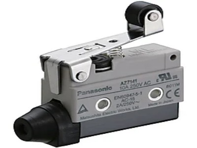
- Check for Physical Damage:
- Inspect the switch housing for cracks, deformation, or corrosion (e.g., broken actuators or rust). Physical damage often directly causes failure.
- For mechanical switches, examine the contacts for oxidation, arcing, or looseness. Contaminated or oxidized contacts lead to poor conductivity.
- Environmental Exposure:
- Verify if the switch is exposed to water, oil, or high temperatures (e.g., above 80°C). Check seals or polyurethane covers for wear or leaks.
Functional Testing
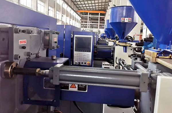
- Operational Consistency:
- If the machine exhibits issues like failure to close molds or ejector plates not resetting (e.g., unresponsive ejector pins), suspect a faulty limit switch.
- Example: A damaged mold-clamping confirmation switch may halt injection cycles.
- Position Calibration:
- Ensure the switch triggers at the correct position. Adjust the activation range to 0.187″–0.250″ (4.75–6.35 mm). Misalignment can cause premature wear or failure.
- Incorrect timing (early/late triggering) leads to defects like short shots or flash.
Electrical Diagnostics
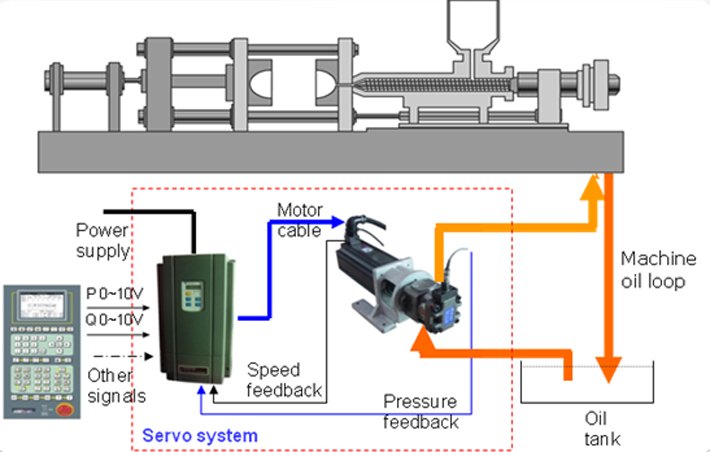
- Multimeter Testing:
- Measure continuity:
- A closed switch should show 0Ω resistance; an open switch should show infinite resistance.
- If voltage persists when the switch is open (e.g., 24V for ejector pin switches), the contacts may be fused or shorted.
- Voltage & Signal Verification:
- Test for proper voltage (e.g., 24V DC for ejector switches). Voltage drops or shorts indicate internal faults.
- Use indicator lights or PLC feedback to confirm signal transmission. No signal or erratic blinking suggests switch failure.
Lifespan & Environmental Factors
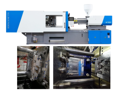
- Cycle Count:
- Most switches have a rated lifespan (e.g., 10 million cycles). High-temperature models (rated for 250°F/121°C) degrade faster. Replace switches nearing their limit.
- Environmental Tolerance:
- Ensure the switch is rated for ambient conditions. For example, oil-resistant switches are critical in hydraulic systems.
Replacement & Maintenance Tips
- Temporary Replacement Test:
- Swap the suspect switch with a known-good unit. If the issue resolves, replace the faulty switch.
- Preventive Maintenance:
- Clean contacts and lubricate mechanical parts every 6 months (more frequently in harsh environments).
Common Failure Scenarios
- Case 1: Mold-clamping switch fails to trigger → Injection aborts.
- Case 2: Ejector pin switch short-circuits → Replace switch or limit rod.
By systematically applying these methods, you can efficiently diagnose limit switch failures and avoid production downtime or mold damage.
What is the function of the limit switch in injection molding?
The limit switch in injection molding serves to verify the positional status of mold components’ movement and send signals to the injection molding machine’s control system, ensuring safe mold closure. Its core functions include:
- Verification of Ejector Plate Retraction
- Adaptability to Environmental and Design Requirements
- Enhanced Reliability Measures
- Signal Integration and Safety Control
- Extended Applications
Verification of Ejector Plate Retraction
The limit switch detects whether the ejector plate has fully retracted to its original position, preventing mold damage caused by incomplete retraction of ejector pins during closure. For example, if the ejector plate fails to retract fully, the limit switch remains open, blocking the “mold close” signal and halting the clamping action. This protection is critical for molds with complex structures like sliders or angled lifters.
Adaptability to Environmental and Design Requirements
- Water/Oil Resistance: Sealed with polyurethane and shielded cables for stable operation in wet or oily environments.
- High-Temperature Tolerance: Standard models withstand 80°C (e.g., Global Thinswitch®), while high-temperature variants handle up to 250°F (121°C).
- Compact Design: Slim profiles (e.g., 3/16″ or ~4.76mm) fit into tight spaces between the ejector plate and return pins.
- Adjustable Trigger Points: Customizable activation ranges (e.g., 0.187–0.250″) via adjustment screws to accommodate varying mold geometries.
Enhanced Reliability Measures
- Series Wiring: Multiple switches are wired in series for large molds to provide redundant verification of ejector plate position, minimizing single-point failures.
- Durability Testing: Most models are tested for >10 million cycles (some exceeding 14 million), reducing maintenance frequency.
Signal Integration and Safety Control
The limit switch connects to low-power mold protection circuits (not high-load systems) and uses SPDT/SPST switching to relay signals. For instance:
- A closed circuit (ejector plate retracted) triggers the machine to proceed with mold closure.
- An open circuit (ejector plate misaligned) interrupts the cycle to prevent damage.
Extended Applications
- Sliding Component Locking: Advanced models (e.g., SmartLock®) integrate mechanical locks to secure mold sliders during ejection while sending position-confirmation signals.
- Mold Height Monitoring: Limits overtravel during mold height adjustments.
Summary: The limit switch ensures safe and precise mold operation by physically validating component positions and providing real-time feedback to the control system. It is a safety-critical component that prevents costly mold damage and ensures production continuity.
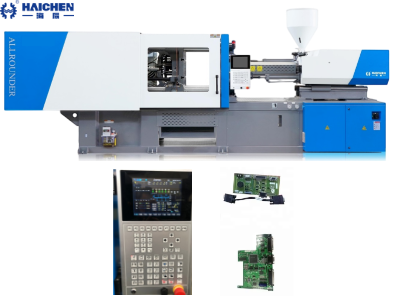
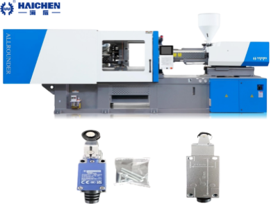
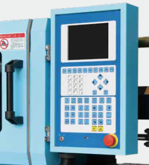
Limit switch of Haichen injection molding machine
Core Features and Technical Specifications of Haichen Injection Molding Machine Limit Switches
- Key Product Series
- Ultra-Thin Limit Switch: Designed to verify the full retraction of mold ejection plates, with a slim profile (3-4mm height) for confined spaces. Adjustable actuation range (3.2-4mm) and mechanical durability exceeding 14 million cycles prevent mold damage caused by foreign objects during closure.
- Liquid-Resistant Limit Switch: Engineered for oily or humid environments, featuring high protection rating to avoid liquid ingress and false triggering. Ideal for use near cooling systems or lubrication components.
- Integrated Slide Retainer & Limit Switch: Combines mechanical locking and position sensing. Captive screw design prevents part loss and supports 10 million cycles, ensuring stability for side-core pulls or sliding mechanisms.
- Technical Advantages
- Extended Lifespan: Mechanical durability reaches tens of millions of cycles (far exceeding standard industrial switches rated for 500,000 cycles).
- Harsh Environment Resilience: High-temperature variants (for heated mold zones) and oil/liquid-proof models adapt to extreme workshop conditions.
- Dual Safety Mechanisms: SPDT (Single Pole Double Throw) switches enable real-time mold status monitoring, cutting signals instantly to prevent collisions or component displacement.

- Primary Applications
- Ejection Plate Verification: Installed in ejection systems to ensure full retraction after mold opening, avoiding closure interference.
- Slide Mechanism Locking: Provides both physical retention and electrical feedback for side-core actions, securing components during high-pressure injection.
- Oil/Heat Zone Protection: Reliable operation near cooling lines or heating units minimizes downtime in polluted or thermally challenging areas.
- Market Differentiation
Compared to generic industrial limit switches (e.g., Honeywell, Omron), Haichen products are optimized for injection molds with:- Space-Saving Design: Ultra-thin profiles fit tight mold cavities without retrofitting.
- Cost-Effective Maintenance: 20x longer lifespan reduces replacement frequency and downtime.
- Industry-Specific Protection: Tailored solutions for oil, heat, and vibration in molding environments.
By the end
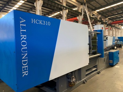
Haichen’s injection molding machine limit switches deliver critical mold protection through ultra-compact sizing, liquid resistance, and extreme durability, addressing precision, high-cycle, and harsh-environment demands in modern production.
Feel free to contact us to get more technical knowledge about injection molding machines.