Every injection molding mold comprises several parts, and every part has a role that supports the effective molding of plastic components. The following summarizes the main parts that constitute the molds. Every injection mocking mold, has subcomponents that work towards the same solution of making a mold which is subdivided into a number of processes.
Each component part of the mold directly relates to the quality of the part produced and the efficiency of the processes carried out. Take for example the mold base, which balances the mold, the cavity, and core of the parts which have to do with the precision of shapes that needs to be produced. Also the runner system governs the flow of the material to be filled. The control of temperature and the system for ejection have big cycle of produce commendably. Components work together as a system and integration of the parts constructed individually is a process that passes several rounds of molding trials to achieve optimal balance.
Every injection molding mold, has subcomponents that work towards the same solution of making a mold which is subdivided into a number of processes. Suffice it to say, an appropriate ratio of the materials and precision which is the molding is also a big factor which affects the quality of the part and working life of the mold. Steel or copper and their alloys usually have a role to play when precision and quality is concerned. Hydraulic efficiency is another factor: the part should be as rigid as possible, mold release features within the part should be at an optimal angle, as well as which helps the signiftantly that has to be followed when cooling and venting.
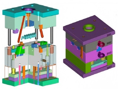
Core injection molding mold
Mold cavity
The mold cavity is the hollow space within the mold that forms the external geometry of a plastic part. When molten plastic is injected into the closed mold, the cavity and core together create the complete shape of the part.
Functions
Defines the part’s shape, surface detail, and dimensional accuracy.Withstands the high pressures (often reaching thousands of psi) and temperatures experienced during the injection process.Integrates with the cooling system to ensure uniform solidification of the plastic.
structure and Position
- Cavity A Side (Stationary Side): This part is fixed to the stationary plate of the injection molding machine. And it does not move during the molding process. It houses the runner system and aligns with the moving side using guide pins and bushings. It also contains cooling channels for circulating coolants.
- Cavity B Side (Moving Side): This side is responsible for opening and closing the mold. It typically contains the ejector system and insert holder, and it mountes on the machine’s movable platen. Proper alignment and movement are crucial for precise part dimensions and smooth release.
Mould core
- Forming the Part’s Internal Structure: The mold core shapes the internal shape of the plastic part (such as holes, threads, and cavities), while the mold cavity defines the external shape. When closed, the two form the complete mold cavity, into which the molten plastic injects to form the part.
- Pressure Resistance: The mold core must withstand the high pressures of the injection molding process (especially the clamping force) to ensure structural stability and dimensional accuracy.
Position and structural design
Located on the B side of the mold (movable mold): The core typically installs on the core side of the mold, opposite the cavity side. After mold opening, the core retreats with the movable mold, and the ejector system ejects the part from the core.
Special structural requirements
- Draft Angle: Designing rounded and beveled edges ensures smooth part demolding.
- Replaceable Inserts: Complex internal features (such as threads) can implement using inserts, reduce overall mold cost and improving maintainability.
- Venting and Cooling: Integrated venting slots require to prevent air holes, and optimize cooling channel design. It will minimize deformation.
Materials and manufacturing processes
Highly wear-resistant materials: Commonly use tool steels (such as P20 and H13) or copper alloys (to improve thermal conductivity and reduce deformation). They are used to withstand high temperatures and high pressures.
Precision machining: Dimensional tolerances are maintained through processes such as CNC and electrical discharge machining (EDM). Surface polishing or electroplating is required to improve mold release.
Inserts
Definition
An insert is a component independent of the mold cavity and core. It is placed manually or automatically into the mold before injection molding to create specific features (such as threads, textures, reinforcements, etc.) on the molded part.
Main Capabilities
- Complex Feature Molding: Create threads, micro-nanostructures, undercuts, or surface textures.
- Enhanced Part Performance: Improve the strength, conductivity, or wear resistance of plastic parts using metal inserts (such as threaded bushings).
- Mold Flexibility and Lifespan: Interchangeable designs allow for quick mold modifications (such as replacing a textured insert), avoiding mold scrapping and reducing maintenance costs.
Basic support structure
Mold Base
Guide and Alignment Components
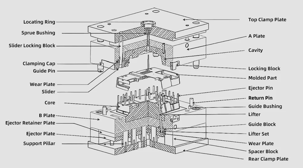
Injection molding and runner system
Sprue System
Cooling System
Ejector System
The ejector system, composed of ejector pins, ejector plate, and knockout rods, is used to remove the molded plastic part from the mold. The design of the ejector system needs to take into account the complexity of the part and the magnitude of the ejection force.
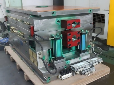
Ejector and Return Mechanism
Ejector System
- Ejector Pins: Push the molded part out of the core.
- Ejector Plates: Secure the ejector pins and provide the propulsion force.
- Return Pins: Return the ejector mechanism to its original position when the mold is closed.
Springs/Ejector Bolts
Assist the ejector mechanism. A combination of compression springs and ejector bolts is common in European designs.
Cooling Channels
Internal water channels
(or combined with baffles/bubblers) regulate mold temperature, shortening molding cycles and reducing deformation.
Vents
Exhaust air from the mold cavity to prevent porosity and burning in parts (mentioning the importance of venting systems).