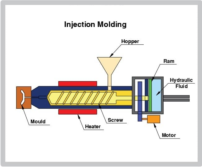
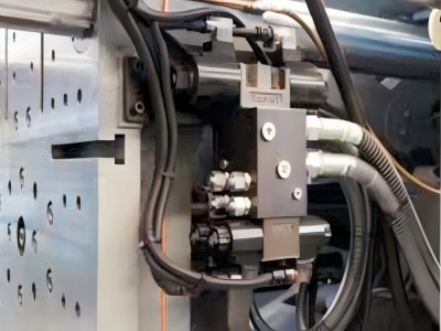
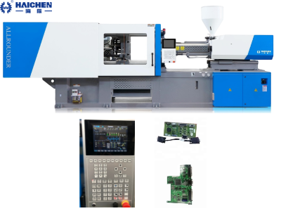
The injection cylinder is a critical component of an injection molding machine, responsible for generating the force needed to inject molten plastic into the mold. Proper maintenance ensures longevity, efficiency, and consistent part quality. With preventive maintenance, you can maintain the value of your injection moulding machine over time while reducing maintenance costs.
Injection molding machine hydraulic cylinders require frequent and thorough inspections to ensure consistent clamping, ejection, and injection pressures. These are extremely important for stable production technology.
Basic injection molding machine hydraulic cylinder maintenance tips are designed to ensure efficient production of molded parts. These tips include preventive maintenance techniques that can identify and correct injection molding problems before they pose a risk to production.
Below are key maintenance practices:
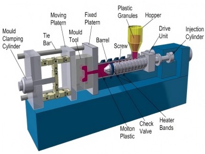
Conventional maintenance and inspection points for hydraulic cylinders of injection molding machines
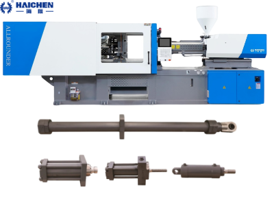
- Regular Inspection
- Hydraulic Fluid Management
- Seal Maintenance
- Piston Rod Care
- Pressure System Checks
- Prevent Contamination
- Alignment and Lubrication
- Monitor Performance
- Training and Documentation
Regular Inspection
- Check for Leaks:
- Inspect hydraulic lines, seals, and connections for oil leaks. Replace worn seals (e.g., O-rings, piston seals) immediately.
- Common leak points: Rod seals, piston seals, and gland nuts.
- Monitor Hydraulic Fluid:
- Ensure fluid levels are adequate and free of contaminants (check for discoloration or debris).
- Replace hydraulic filters every 3–6 months or as per manufacturer guidelines.
Hydraulic Fluid Management
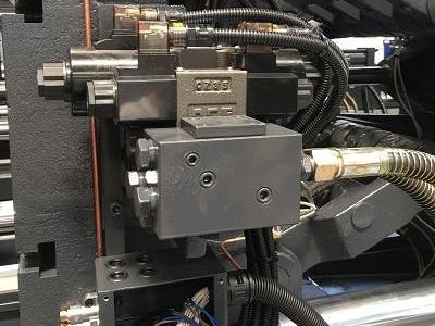
- Use Recommended Fluid:
- Follow the manufacturer’s specifications for viscosity and grade (e.g., ISO VG 46).
- Avoid mixing different fluid types.
- Prevent Overheating:
- Maintain fluid temperature between 40–50°C (104–122°F).
- Use coolers or heat exchangers to dissipate excess heat.
Seal Maintenance
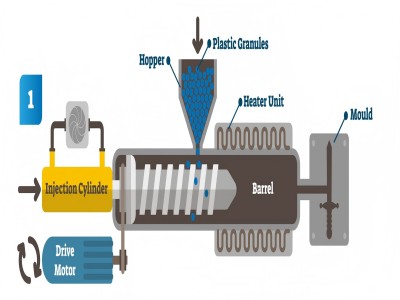
- Replace Worn Seals:
- Symptoms of seal failure: Oil leaks, pressure drops, or inconsistent injection speeds.
- Use manufacturer-approved seals to ensure compatibility.
- Lubricate Seals:
- Apply a thin layer of hydraulic-compatible grease during assembly to extend seal life.
Piston Rod Care
- Clean and Protect:
- Wipe the piston rod daily with a lint-free cloth to remove dust or debris.
- Apply a corrosion-resistant coating if the rod shows signs of rust.
- Check for Damage:
- Inspect for scratches, pitting, or bending. Replace damaged rods to prevent seal wear.
Pressure System Checks
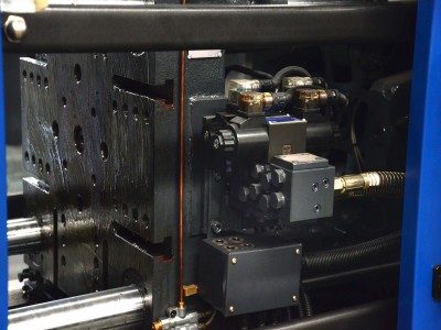
- Calibrate Pressure Settings:
- Verify injection and holding pressures match machine specifications.
- Overpressure can strain the cylinder and cause leaks.
- Test Relief Valves:
- Ensure pressure relief valves function correctly to prevent system overload.
Prevent Contamination
- Keep the System Clean:
- Use desiccant breathers on hydraulic reservoirs to prevent moisture ingress.
- Install magnetic plugs to capture metal particles.
- Purge the System:
- Flush hydraulic lines during fluid changes to remove sludge or debris.
Alignment and Lubrication
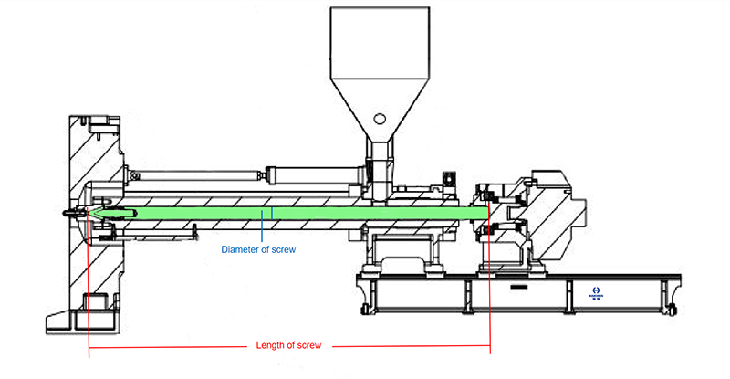
- Check Cylinder Alignment:
- Misalignment causes uneven wear on seals and rods. Use dial indicators to verify alignment with the injection unit.
- Lubricate Moving Parts:
- Apply grease to guide rods and bushings as per the maintenance schedule.
Monitor Performance
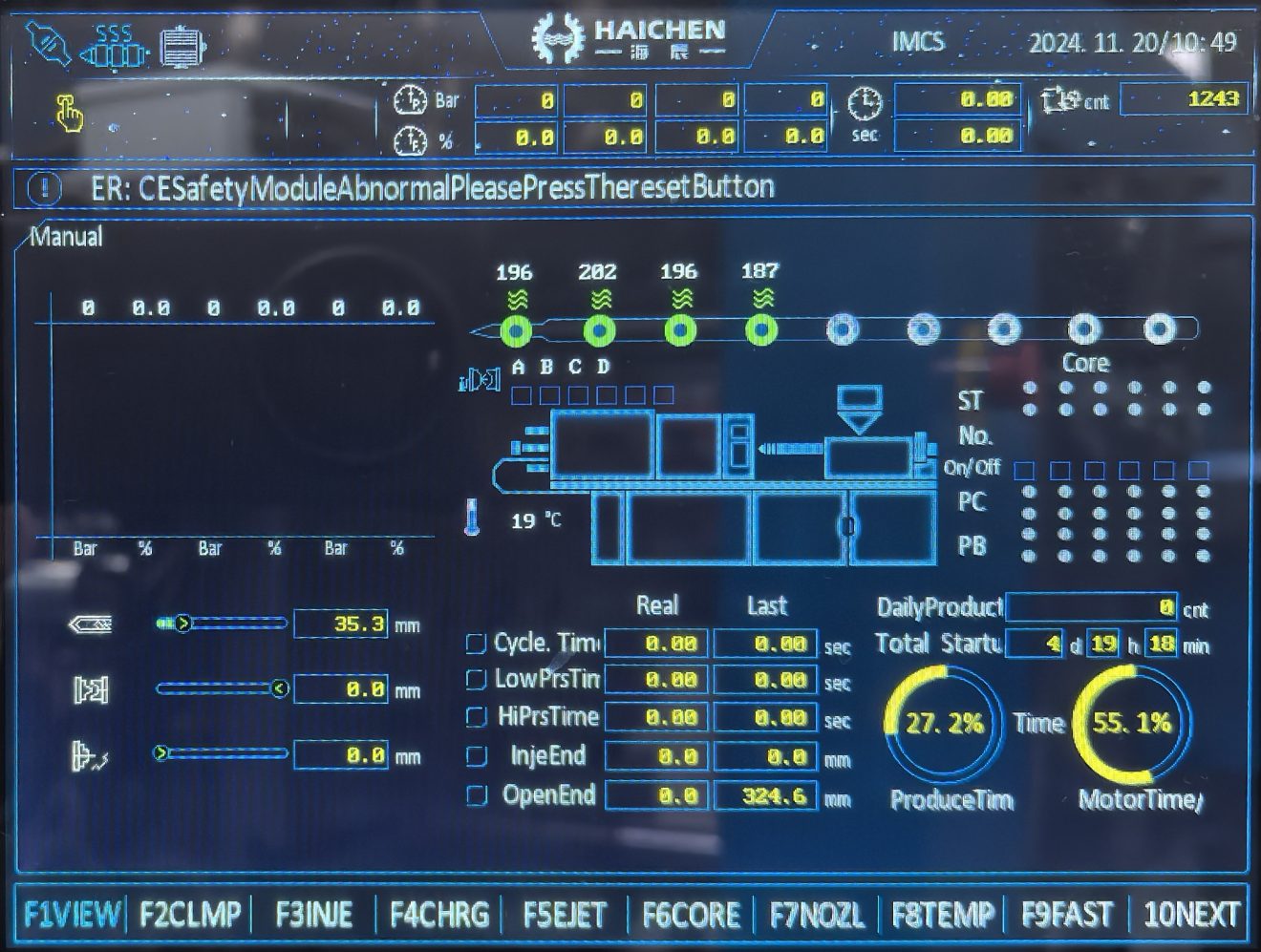
- Track Cycle Times:
- Gradual increases in cycle time may indicate cylinder wear or pressure loss.
- Listen for Unusual Noises:
- Knocking or grinding sounds suggest air in the system or worn components.
Training and Documentation
- Train Operators:
- Ensure staff recognize early signs of cylinder issues (e.g., leaks, pressure fluctuations).
- Maintain Records:
- Log maintenance activities, fluid changes, and part replacements for proactive planning.
Common Issues & Solutions
| Issue | Cause | Solution |
|---|---|---|
| Hydraulic Fluid Leaks | Worn seals, loose fittings. | Replace seals; tighten connections. |
| Slow Injection | Low fluid level, clogged filter. | Top up fluid; replace filter. |
| Overheating | Excessive pressure, poor cooling. | Check relief valves; clean coolers. |
| Seal Degradation | Contaminated fluid, high temps. | Replace fluid; inspect for overheating. |
Preventive Maintenance Schedule
| Task | Frequency |
|---|---|
| Inspect seals and leaks | Daily |
| Check hydraulic fluid | Weekly |
| Replace filters | Every 3–6 months |
| Flush hydraulic system | Annually |
| Calibrate pressure valves | Annually |
Why It Matters
Neglecting injection cylinder maintenance leads to:
- Costly Downtime: Seal failures or pressure drops halt production.
- Poor Part Quality: Inconsistent pressure causes defects like short shots or sink marks.
- Safety Risks: Hydraulic leaks or overheating can endanger operators.
By following these tips, manufacturers ensure reliable performance, extend equipment lifespan, and maintain consistent product quality. Partner with certified technicians for complex repairs or overhauls.
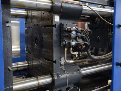
Injection Cylinders structure in Injection Molding machine
The injection cylinder in an injection molding machine is a critical component responsible for generating the force required to inject molten plastic into the mold. Its structure and components are designed to ensure precise control, durability, and efficient operation. Below is a detailed breakdown of its structure, key components, and their functions:
- Key Components of the Injection Cylinder
- Working Principle
- Types of Injection Cylinders
- Key Design Considerations
- Integration with the Injection Unit
- Common Failure Modes & Solutions
- Maintenance Best Practices
- Importance in Injection Molding
- Example Specifications
Key Components of the Injection Cylinder
Cylinder Body
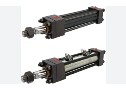
- Material: High-strength steel or alloy to withstand extreme hydraulic pressures (up to 2,000 bar).
- Function: Houses the piston and hydraulic fluid, providing structural integrity.
Piston
- Material: Hardened steel or chrome-plated for wear resistance.
- Function: Converts hydraulic pressure into linear motion to drive the screw forward during injection.
- Design:
- Single-acting (pressure applied on one side) or double-acting (pressure on both sides for bidirectional control).
Piston Rod
- Material: Polished stainless steel or chrome-plated for smooth movement and corrosion resistance.
- Function: Connects the piston to the injection screw, transmitting force to push molten plastic into the mold.
Seals and Gaskets
- Types:
- Rod seals: Prevent hydraulic fluid leakage around the piston rod.
- Piston seals: Ensure pressure integrity between the piston and cylinder wall.
- Wiper seals: Keep contaminants out of the Injection molding Cylinder.
- Material: Nitrile rubber, polyurethane, or PTFE for high-temperature resistance.
Hydraulic Ports
- Inlet/Outlet Ports: Allow hydraulic fluid to enter and exit the cylinder.
- Function: Control the piston’s movement via directional valves.
Sensors
- Position Sensors: Monitor piston location for precise stroke control.
- Pressure Sensors: Ensure optimal injection pressure (e.g., 500–1,500 bar).
Working Principle
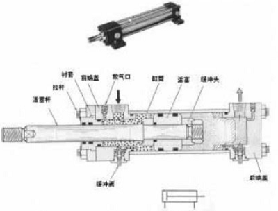
- Hydraulic Fluid Supply: A pump delivers pressurized hydraulic fluid to the Injection molding Cylinder.
- Piston Movement:
- During injection, fluid enters the rear chamber, pushing the piston and screw forward.
- During retraction, fluid flows to the front chamber, pulling the piston back.
- Force Transmission: The piston rod transfers force to the screw, injecting molten plastic into the mold.
Types of Injection Cylinders
| Type | Description | Applications |
|---|---|---|
| Single-Acting | Hydraulic pressure acts on one side; return via spring or external force. | Low-force, simple systems. |
| Double-Acting | Pressure applied to both sides for bidirectional control. | Standard in most modern machines. |
| Tandem Cylinders | Multiple cylinders linked for higher force output. | Large machines (>3,000 tons clamping). |
Key Design Considerations
- Bore Diameter: Larger bores generate higher force (force = pressure × area).
- Stroke Length: Determines the screw’s travel distance (adjusted for part size).
- Seal Compatibility: Must withstand high temperatures (up to 300°C) and abrasive additives.
Integration with the Injection Unit
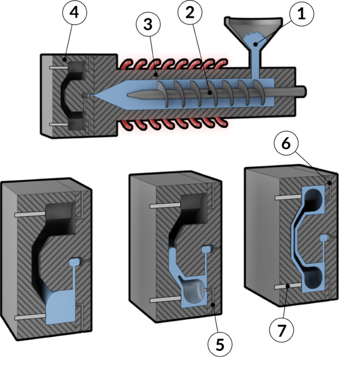
- Screw Connection: The piston rod attaches to the reciprocating screw, which melts and injects plastic.
- Hydraulic System: Includes pumps, valves, and accumulators to regulate fluid flow.
- Control System: PLCs adjust pressure and speed for optimal injection profiles.
Common Failure Modes & Solutions
| Issue | Cause | Solution |
|---|---|---|
| Hydraulic Leaks | Worn seals, cracked cylinder. | Replace seals; inspect cylinder for damage. |
| Slow Injection | Low fluid pressure, clogged ports. | Check pumps; clean hydraulic lines. |
| Piston Rod Scoring | Contaminants or misalignment. | Polish rod; realign cylinder. |
Maintenance Best Practices
- Inspect Seals Regularly: Replace every 6–12 months or as per wear indicators.
- Monitor Hydraulic Fluid:
- Maintain cleanliness (ISO 4406 Class 18/16/13 or better).
- Change fluid every 2–3 years or as specified.
- Check Alignment: Ensure the piston rod and screw are coaxial to prevent uneven wear.
- Lubricate Guides: Apply grease to bushings and rod surfaces.
Importance in Injection Molding
- Precision: Ensures consistent shot size and pressure for defect-free parts.
- Efficiency: Optimizes energy use by balancing speed and force.
- Durability: Robust construction minimizes downtime in high-volume production.
Example Specifications
| Parameter | Range |
|---|---|
| Bore Diameter | 50–500 mm |
| Stroke Length | 200–2,000 mm |
| Max Pressure | 1,500–2,000 bar |
| Force Output | 50 kN–10 MN (5–1,000 tons) |
The injection cylinder’s design and maintenance are pivotal to the performance of an injection molding machine.
Its ability to deliver precise, high-force linear motion directly impacts part quality, cycle times, and operational costs. By understanding its structure and adhering to maintenance protocols, manufacturers can ensure reliable, long-term performance.
For specialized applications (e.g., high-speed thin-walled parts or large automotive components), custom Injection molding Cylinder designs may be required to meet specific force and speed demands.
You are welcome to contact Haichen by email or phone at any time to get more technical support related to injection molding machines.