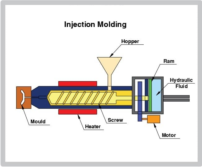
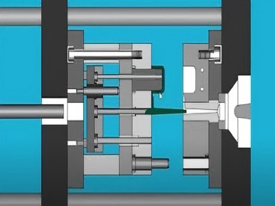
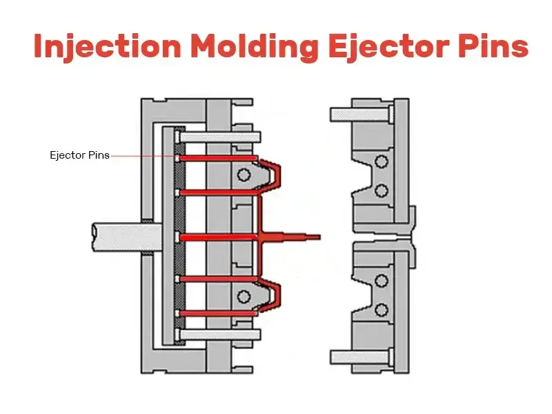
Ejector pins in injection molding are crucial for pushing molded parts out of the mold after cooling.
Various types exist, each suited for different part geometries and molding conditions, including straight, shoulder, sleeve, and blade ejector pins.
Considerations for choosing the right ejector pin include part geometry, molding material, temperature requirements, surface finish, and mold design.
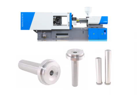
The main types and structural characteristics of ejector pin in injection molding
- Dome pin (standard flat-headed thimble)
- Flat thimble (blade thimble)
- Thimble with support (double-section thimble)
- Cylinder needle (push tube thimble)
- Oblique thimble
- Push block ejector pin and air ejector pin
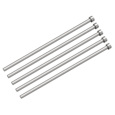
Dome pin (standard flat-headed thimble)
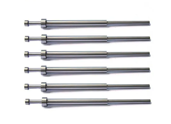
Structural features: cylindrical, round cross-section, simple processing, low cost and high degree of standardization.
It can be divided into two forms: unsupported thimble (diameter ≥ 2.5mm) and supported thimble (diameter < 2.5mm).
Application scenario
It is suitable for flat or regular surface demoulding of most products, especially near bone position, column position and hole groove.
Advantages: easy maintenance, high matching accuracy, accounting for more than 99% of the mold ejection system.
Flat thimble (blade thimble)
The cross-section is rectangular or square, and the head can be designed as reinforced.
Such as semi-square cross-section semi-cylindrical support) to improve strength.
Application scenario: Deep bones, narrow edges, or transparent parts that cannot be used for dome pins.
Such as areas with a thimble function, also have an exhaust function.
Disadvantages: high processing cost (wire cutting or Y-CUT process required), easy to wear, difficult maintenance.
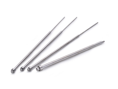
Thimble with support (double-section thimble)
Structural features: Add a reinforcing section (bracket length) at the root of the thimble to improve the bending strength of the small-diameter thimble.
Recommended for diameters < 3 mm.
Design points: The bracket length needs to be matched with the ejector pin hole to avoid interference.
And it is often used in occasions with high compressive strength requirements.
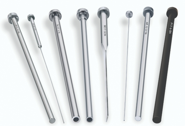
Cylinder needle (push tube thimble)
Structural features: hollow casing structure, suitable for Boss column demoulding.
Cylindrical structure with a depth of more than 10mm is better.
Advantages: Reduced processing costs and improved exhaust.
But with a small platen that holds the drum in place to prevent displacement.
Oblique thimble
Structural features: inclined installation, the ejector surface needs to be ground in the shape of “+”or parallel slots to prevent the product from sliding.
In fact, it is suitable for demoulding complex curved surfaces or undercut structures.
Push block ejector pin and air ejector pin
For push block ejectors, manufacturers typically employ them in deep-cavity molds or for products with significant side-wall sticking force.
These systems effectively distribute local stress through their large-area contact design.
When considering air-assisted ejection, the system uses compressed air to help remove thin-walled or deformable parts.
This approach requires careful integration with precision sealing components to maintain proper function.
Core considerations for ejector pin design in injection molding
- Layout principle
- Material Selection & Heat Treatment
- Size and tolerance control
- Lubrication & Maintenance
Layout principle
Balanced ejection force
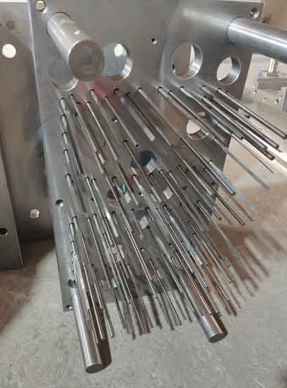
Symmetrical arrangement in areas with large demoulding force such as four corners, deep bones, columns to avoid product deformation.
Avoidance structure
Keep a distance of ≥4mm from the cooling channel, and leave a margin of 1.5mm ≥ from the core steel to avoid setting across steps or inclined planes.
Appearance requirements
Transparent parts or high-gloss products need to hide the traces of thimbles and avoid being arranged on the light transmission or appearance surface.
Material Selection & Heat Treatment
Common materials include SKD61 with high temperature resistance up to 700°C and SKH51 (known for its high hardness), as well as H13 (valued for its wear resistance).
To maximize component performance, manufacturers apply surface nitriding treatment, which significantly boosts wear resistance.
After completing the quenching process, they must implement full tempering to effectively relieve residual stress.
For optimal material performance, engineers should control SKD61 surface hardness to HRC46-48, or alternatively.
They can achieve HV1000±100 hardness through precision nitriding treatment.
Size and tolerance control
Regarding diameter selection, large diameter ejector pins (typically φ4-φ6mm) are commonly used, while small diameter pins (<2.5mm) require additional structural support.
For length calculation, precise measurement of the total distance from the ejector plate to the parting surface is essential.
Taking into account the combined thickness of the mold pin, ejector plate, and mold core height – with a 0.5mm safety margin to prevent insufficient ejection.
Concerning fit tolerance, the ejector pin hole requires tight specifications: 0.01/0.02mm tolerance with positional accuracy of ±0.02-±0.05mm.
Additionally, surface roughness must be optimized to minimize friction during operation.
Lubrication & Maintenance
Lubrication system: Use fluorine grease and other high temperature-resistant lubricants to avoid oil contamination of transparent parts or electroplated parts.
we recommend dry lubrication to reduce carbon formation.
Regular maintenance: check for wear, clean surfaces, lubricate critical areas, and complex repairs are carried out by professionals.
Ejector Pin Failure Modes and Precautions
Fracture or Bending
Causes: Uneven Ejection Force, Material Fatigue, Improper Heat Treatment.
Recommended Solutions
First, optimize the thimble layout pattern and increase the quantity to balance ejection forces.
For high-stress applications, implement double-section thimbles or reinforced flat thimbles to strengthen critical areas.
Additionally, enhance surface polishing to reduce friction or increase the demolding angle by 0.5-1° to improve release.
Thimble jamming or ablation
Causes: too small clearance, insufficient lubrication, high temperature environment.
Countermeasures: avoid 0.1mm in the middle section of the thimble hole, use 700°C resistant materials (such as GT30 mold steel).
And apply high-temperature resistant lubricating paste regularly.
Product surface defect
Cause: The thimble mark is too deep or the position is improper.
Solution: Optimize the shape of the thimble head (such as D-shaped anti-rotation design).
Increase the draft angle; Adjust the ejection speed and pressure.