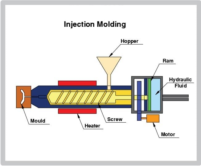
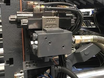
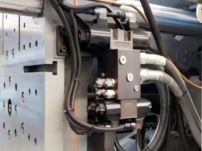
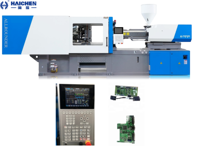
The precise positioning of the tie bars is extremely important during the operation of an injection moulding machine. It ensures stability and accurate alignment between the moving platen and the fixed platen. During the injection process, the tie bars apply clamping force while guiding the movement of the moving platen, ensuring that the mould closes evenly and accurately.
Tie bars – support and align the platens, which in turn support the mold. The spacing between the tie bars limits the size of the mold that can be placed in the injection molding machine.The core significance of Tie bar placement is to balance mold size, clamping force distribution, equipment stability and production efficiency.
We believe that there are still many details about the tie rod of the injection molding machine that we need to list for you one by one. Let’s take a look at the technical details below.
Welcome to visit our YouTube channel to view more technical videos
Detailed explanation of the support provided by injection moulding machine tie bars for the machine’s clamping components
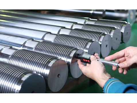
The layout and spacing of tie bars in injection molding machines are critical to equipment performance and product quality. Here’s why:
- Mold Size Limitations
- Clamping Force Distribution
- Machine Rigidity and Stability
- Production Flexibility and Efficiency
- Specialized Applications
Mold Size Limitations
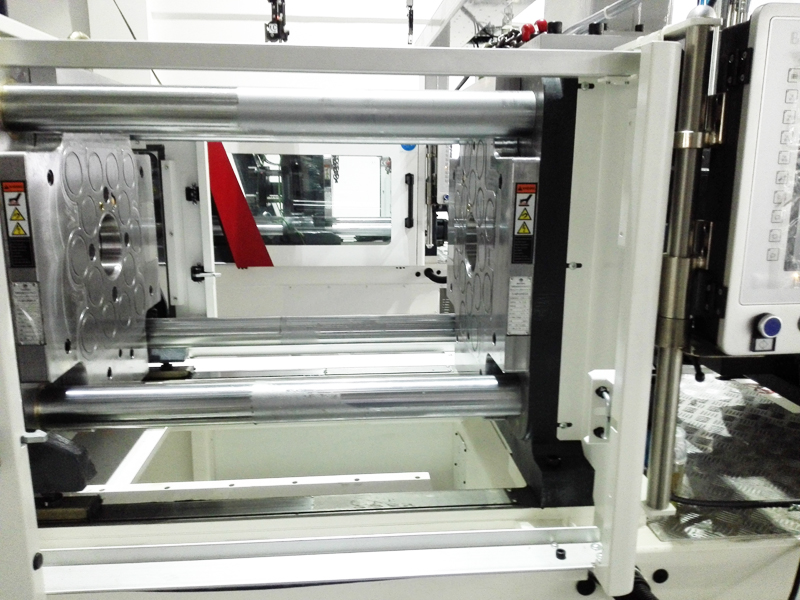
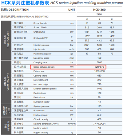
Tie bar spacing (horizontal and vertical distances) directly determines the maximum mold size that can be installed. For example:
- Mold width/height must be less than half the tie bar spacing; otherwise, the mold cannot fit.
- Oversized molds may require rotating the mold or switching to a larger machine.
- Tie-bar-free clamping technology eliminates tie bars, allowing larger molds (e.g., multi-cavity or partial-surface molds) to be used without size restrictions.
Clamping Force Distribution
Traditional tie bars can lead to uneven clamping force distribution:
- Tie-bar-free systems use patented force dividers to ensure uniform clamping force across the entire platen, even at mold edges, reducing part warpage or flash.
- Uneven tie bar lengths or thermal expansion (e.g., fatigue from cyclic stress or temperature changes) may overload individual tie bars, risking breakage.
Machine Rigidity and Stability
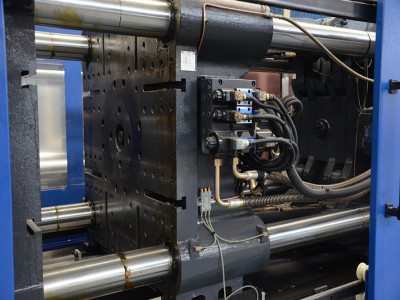
Tie bar rigidity directly impacts machine stability:
- Insufficient rigidity causes platen deflection under high clamping pressure, leading to inconsistent part quality.
- Micro-level tie bar elongation (8–27 µm) can indicate clamping force fluctuations, requiring real-time sensor monitoring.
- Tie-bar-free designs (e.g., ENGEL’s “guidelineless” moving platen) reduce lateral forces, improving mold longevity and stability.
Production Flexibility and Efficiency
- Faster mold changes: Tie-bar-free machines allow robots to access molds from the side, bypassing tie bar obstructions.
- Space optimization: Compact tie-bar-free machines suit cleanrooms or space-constrained facilities and enable smaller machines to handle larger molds, reducing capital costs.
- Lower maintenance: Traditional tie bars require frequent checks for elongation and force alignment, while tie-bar-free systems minimize downtime from tie bar wear.
Specialized Applications
- Multi-color molding and complex molds: Tie-bar-free designs accommodate intricate or asymmetrical mold layouts.
- Medical-grade parts: Eliminating tie bars reduces oil leakage risks, enhancing cleanliness for sterile environments.
In simple terms
Tie bar placement balances mold size compatibility, clamping force uniformity, machine stability, and operational efficiency. While traditional tie bars require strict mold-machine size matching, tie-bar-free clamping breaks these limits, offering advantages for high-precision, high-efficiency production. Choosing between tie bar and tie-bar-free systems depends on mold design, process requirements, and cost considerations.
How to do Tie bar placement in injection molding machines?
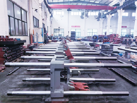
Proper Tie Bar Placement in Injection Molding Machines
Correct tie bar installation is critical for mold stability and product quality. Below is a detailed guide based on technical specifications and best practices:
- Pre-Installation Preparation
- Installation Procedure
- Post-Installation Maintenance & Optimization
- Key Notes
Pre-Installation Preparation
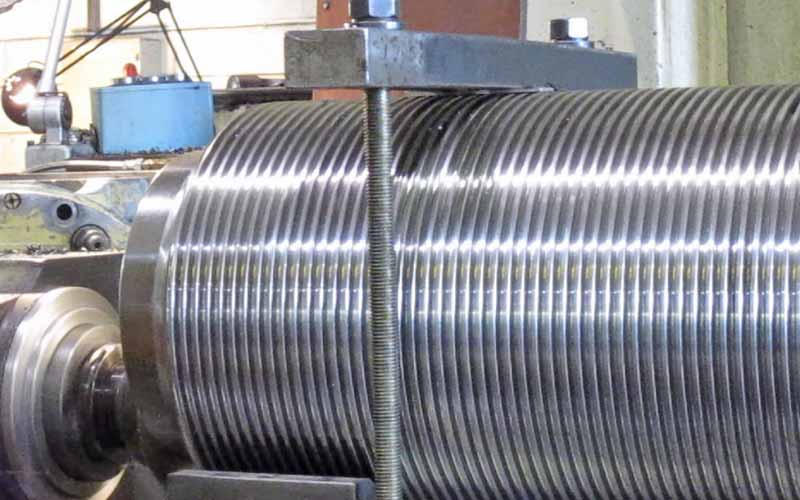
- Verify Mold Dimensions and Tie Bar Spacing
- Ensure the mold width/height is smaller than the horizontal/vertical tie bar spacing. For example, mold width should be ≤50% of horizontal spacing, with a 25–50mm buffer on each side to avoid collisions.
- Check the machine’s technical specifications. If the mold exceeds limits, resize it or use a machine with larger tie bar spacing.
- Inspect Tie Bars and Platens
- Check tie bars for deformation or wear. Ensure platens are flat.
- For toggle-type clamping systems, validate load uniformity across all tie bars to prevent uneven stress (e.g., mold crushing or flash).
Installation Procedure
- Mold Mounting and Alignment
- Use a crane to lift the mold. Align the mold’s center of gravity with lifting rings and close the parting surface fully. For heavy molds (>200kg), use balance beams for precise alignment.
- Align the mold’s locating ring with the stationary platen’s locating hole (gap tolerance: ~0.1mm). Slowly close the moving platen until it contacts the mold without applying clamping force.
- Adjust Tie Bar and Platen Parallelism
- Use a spirit level on tie bars to check parallelism (front/back and left/right). Adjust shock absorber pads or platen screws to correct deviations.
- For tie-bar-free (TBF) machines, use support frames and wedges to secure the mold, ensuring full contact between the frame and platens.
- Mold Fixation and Load Testing
- Secure the mold to moving/fixed platens using clamps and bolts. Avoid direct impacts on tie bars to prevent surface damage.
- After initial clamping, measure tie bar elongation with dial gauges (max difference: ≤0.05mm). If uneven, re-align the mold or check platen flatness.
Post-Installation Maintenance & Optimization
- Routine Checks and Calibration
- Monitor tie bar elongation and clamping force regularly. Use strain sensors for real-time feedback to optimize V/P switching and part quality.
- Clean mold areas to prevent debris from affecting tie bars or platens.
- Special Scenarios
- Stack Molds: Install lateral support frames and gear-rack drives for synchronized layer movement. Remove supports before mold extraction.
- Vertical Insert Molds: Add guide mechanisms and align on rotary tables (alignment error <0.05mm).
Key Notes
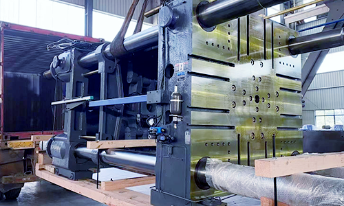
- Material Selection: Use high-strength alloy steel (e.g., EN19/4140) for tie bars, hardened to resist tensile stress.
- Tie-Bar-Free (TBF) Systems: Improve cleanliness and automation compatibility but require robust frame support.
By following these steps, you ensure precise tie bar placement, enhancing molding efficiency and product consistency.
Adjustments may be needed based on machine models and mold designs.

Contact Haichen and let us answer more technical questions about injection molding machines for you.