Thank you for choosing and buying our HAICHEN die casting machine. Sincerely hope that our die casting machines bring you with good harvest and high development. After purchasing the die casting machine, please read our instruction manual seriously, it can make you have a better and quick underestimating of our machine structure, performance and adjustment, so as to do machine installation and put it into use smoothly.
The hydraulic system of a cold chamber die casting machine consists of hydraulic pumps, motors, oil, accumulators, hydraulic valves, operating cylinders (mold closing cylinders, injection cylinders, injection pressurizing cylinders and ejector cylinders) and mold core pulling cylinders that work together to provide power and control for the operation of the machine. These components work together to provide the power, control and motion necessary for the effective operation of the cold chamber die casting machine.
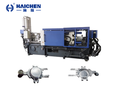
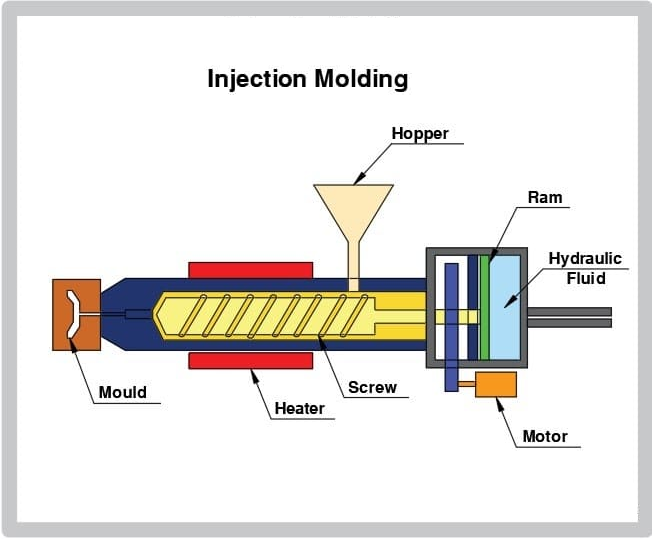
Die casting machines are predominantly hydraulic. Hydraulic systems in die casting machines control the injection process of molten metal into the die with precise speed and force. Furthermore, they also contribute to temperature control within the mold cavity, ensuring optimal casting conditions.
Hydraulic power unit:
This unit includes below items:
- Hydraulic pump
- Motor
- Tank and associated controls
Hydraulic pump:
A hydraulic pump is usually a positive displacement pump, used to pressurize the hydraulic oil. It is available in various types such as gear pumps, vane pumps, or piston pumps. The hydraulic pump is designed as a double vane pump to supply pressure to the system, which ensures the running speed of the machine, reasonably distributes the pressure, and saves power.
When the power cylinder works, the two pumps supply oil at the same time with a high flow rate, and the system pressure is low, about 3MPa.
When the power cylinder stroke is about to end and the system pressure reaches or exceeds 5MPa, the oil is supplied by only one pump and the high-flow pump is automatically unloaded. The oil supply pressure of the small flow pump depends on the action of each cylinder, and the mold closing and accumulator charging are set by the touch screen. Therefore, the motor power can be reasonably distributed.
In addition, when the system pressure reaches the rated value of 13MPa, the high-pressure pump, which is controlled by a preset delay time, is also unloaded. Since the output oil pressure (pressure) is low when the pump is on-load, it can be fed directly to the water cooler to minimize power loss and reduce oil temperature.
Motor:
The electric motor drives the hydraulic pump, converting electrical energy into mechanical energy so that the pump produces hydraulic pressure.
Reservoir:
The reservoir stores hydraulic fluid and provides an oil source for the pump. It also helps dissipate heat and allows the fluid to expand and contract.
Accumulator:
An accumulator is an auxiliary energy storage device in a hydraulic system. It stores hydraulic energy in the form of a pressurized fluid. The accumulator compensates for fluctuations in the hydraulic system by providing additional power and flow during peak demands.
The first and second stage rapid injection is activated by SQ14 and SQ13 travel switches, then the direction of the oil circuit is changed by two-position four-way solenoid valves, the large-diameter cone valve opens, and the high-pressure oil in the accumulator is released into the injection cylinder while the oil is returned to the injection piston chamber, and a large amount of return oil is discharged to the tank through the quick-discharge cartridge valve to produce an instantaneous rapid oil injection.
In addition, the first fast and the second fast flow adjustments can be realized through the relative handle to adjust the fast injection speed to meet the die-casting requirements.
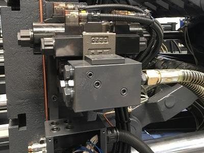
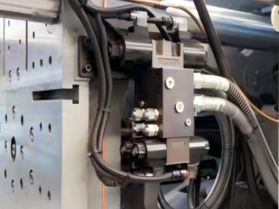
Hydraulic valve:
Different types of hydraulic valves are used to control the flow, pressure, and direction of hydraulic fluid.
Directional Control Valves: These valves control the direction of fluid flow in a hydraulic system. They determine the movement and positioning of hydraulic actuators. Directional control valves can be operated manually or controlled electronically through solenoid valves
Pressure Control Valves: Pressure control valves regulate the hydraulic pressure in the system. They ensure that pressure is maintained within safe operating limits.
Flow Control Valves: Flow control valves regulate the flow rate of hydraulic fluids. They precisely control the speed of the actuator and the distribution of flow within the system. Flow control valves can be adjustable or fixed orifice plates, needle valves, or flow control cylinders.
Proportional Control Valves: These valves provide variable control of flow and pressure by responding to electronic control signals. They allow for fine-tuning and precise control during the die-casting process.
Hydraulic fluid pressure, flow, and mold opening and closing hydraulics are controlled by dual proportional valves and a common low-pressure relief system to form a hydraulic control and switching circuit with pressure regulation based on the type of logic.
Hydraulic directional valves, pressure valves, cartridge valves, etc. are all domestic standard hydraulic valves, in line with international common standards, and easy to replace and maintain.
Hydraulic fluid:
Hydraulic fluid (usually oil) is stored in the tank. It is used as a medium for transmitting power and lubricating the components of the hydraulic system.
hydraulic cylinder:
The actuators in a cold chamber die casting machine are usually hydraulic cylinders. These cylinders convert hydraulic pressure into linear motion to control a variety of machine operations, such as the movement of injection plungers, clamping mechanisms, and ejector systems.
Filtration System:
Filtration is critical to maintaining the cleanliness of the hydraulic fluid to prevent contamination from damaging system components. Filtration systems typically include filters, strainers, and possibly heat exchangers to remove particles and control the temperature of the hydraulic fluid.
Pressure transducers and gauges:
Pressure transducers and gauges are used to monitor and measure hydraulic pressure at various points in the system. They provide feedback to the control system for precise control and to ensure that the system operates within safe limits.
Control system:
The control system manages the operation of the hydraulic system. It may include electronic controllers, sensors, and actuators. The control system receives inputs from a variety of sensors and uses these inputs to regulate the operation of valves, actuators, and other components to ensure coordinated and precise movement in the die casting process.
Notes:
The injection control hydraulic system consists of a three-position four-way electro-hydraulic valve (adjustable flow), a quick-drain hydraulic control valve (standard cartridge valve), a large-diameter quick injection cartridge valve, a solenoid valve, and an injection eccentric manual control valve.
The adjustment of oil injection pressurization is realized by the relative pressure-reducing valve on the hydraulic block after the oil injection pressurization cylinder.
When adjusting the eccentric position of the injection, pull up and down the manual reversing valve handle on the lower part of the injection pressurized cylinder at the end of the seat, so that the vertical guiding slider of the gantry moves up and down.
Note: Before adjustment, loosen the 12 M16 hexagonal bolts on the left and right fixed plates of the door frame and move the slider into the door frame. Replaceable housings with different eccentric heights are available (customized housings).
Before adjusting the injection eccentricity, the injection rod must be removed.
The hydraulic control system of the oil injection pressurization system consists of a piston accumulator, superimposed throttle valve, sequence valve, and electro-hydraulic reversing valve. When the pressure inside the oil injection cylinder rises, the sequence valve opens and the electro-hydraulic reversing valve works quickly, i.e. the large-diameter cartridge valve opens quickly, and the pressure inside the accumulator is immediately released to the pressurized piston, which is instantly and quickly pressurized.
Set the main parameters of flow adjustment on the touch screen to control the pressure, flow, and unloading of the hydraulic system.
Common faults in hydraulic systems
include oil leakage, hydraulic pump failure, pipeline leakage, etc. Oil leakage may be caused by external or internal reasons, and needs to be solved by isolation valves and other methods. Hydraulic pump failure may be caused by incorrect steering, improper adjustment or damage of the overflow valve, etc., and the faulty parts must be gradually isolated and eliminated.
Maintenance and inspection of hydraulic systems
There are important links to ensure their stable operation. Routine inspections should be performed every day to promptly detect and resolve potential problems. Regular inspections include checking the tightness and leakage of hydraulic components and replacing various sealing components promptly. In addition, the hydraulic system needs to be cleaned regularly, and the hydraulic oil and filters need to be replaced to prevent contaminants from accumulating and maintain proper flow and pressure.
Conclusion
The hydraulic and electrical systems of the Haichen C series cold chamber die casting machine adopt components from well-known European, American, and Japanese manufacturers, with a reasonable product structure design and safe and reliable operation.Haichen is one of the professional cold chamber die casting machine manufacturers.