Optimizing injection molding tolerances for precision involves a multi-faceted approach that encompasses design, material selection, tooling, and process control.
Achieving tight tolerances requires careful consideration of these factors and implementing robust quality assurance measures throughout the process.
Part designers add tolerances to CAD files to tell an injection molder the amount of variation that’s allowed.
In turn, injection molders use tolerances during design for manufacturability (DFM) reviews and to make tooling and processing decisions.
As a rule, parts with tighter tolerances are more expensive because they have stricter tooling and processing requirements.
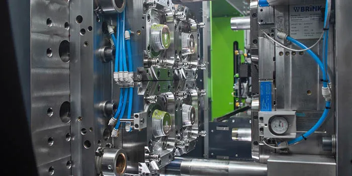
What Is Injection Molding Tolerances?
Injection molding tolerances are acceptable variances of specified dimensions that, if exceeded, will cause the molded part to not function or perform its operational expectation.
These tolerances are important where molded parts are to form part of larger assemblies that require more demanding fits.
When the mold tolerance for a certain part is specified to be within ±0.005 inches.
It means that the part can be more than or less than the specifications in its design by 0.005 inches and still be considered acceptable.
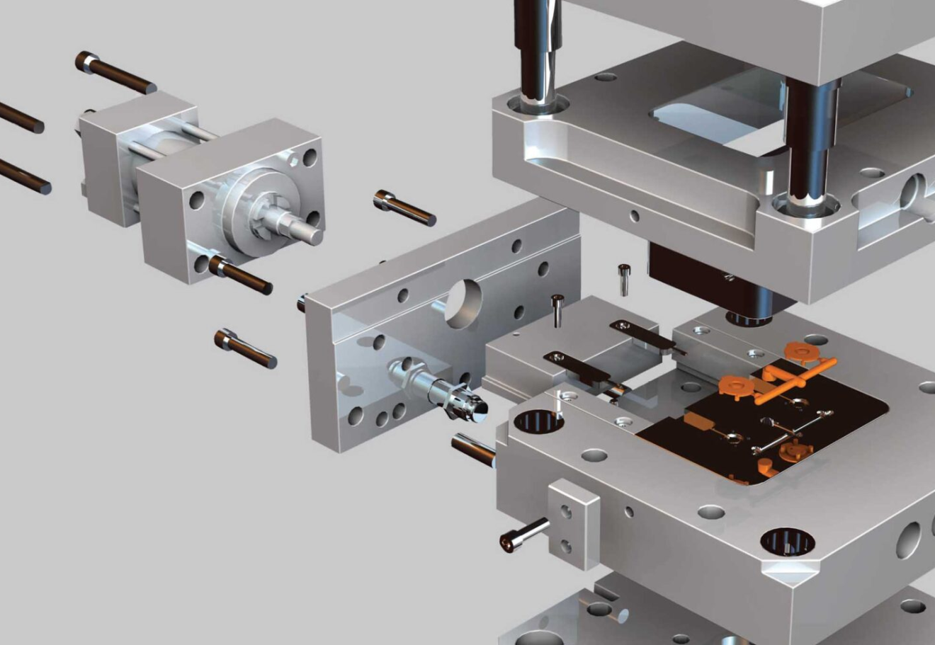
Injection Molding Tolerances
- Definition of Tolerance
- Tolerance Grade
Basic Concept Definition of Tolerance
Tolerance Grade
Tolerance type: including dimensional tolerance, straightness/flatness tolerance, aperture tolerance, etc.
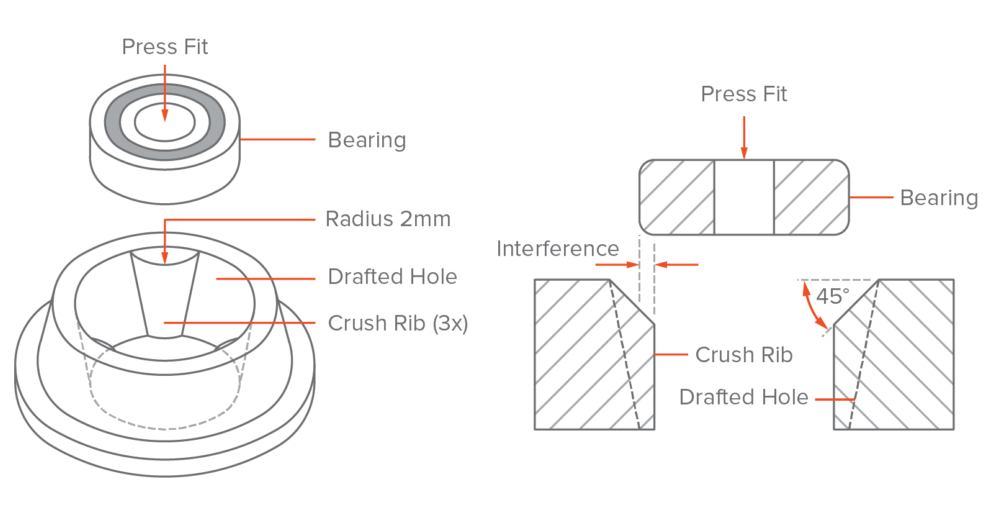
The core factors that affect tolerances
- Material properties
- Coefficient of Thermal Expansion
- Flowability
- Mold Design
- Process Parameters
Material properties
Shrinkage difference: The shrinkage of crystalline materials (such as PP and PA) is significantly higher than that of amorphous materials (ABS, PC).
For example, PP can shrink 1.5-4%, while ABS is only 0.5-1.6%.
Coefficient of Thermal Expansion
Temperature fluctuations cause material expansion/contraction, such as PMMA has a coefficient of thermal expansion of 7×10⁻⁵/°C.
And tolerances need to be controlled in a high-temperature environment.
Flowability
High-flow materials like LDPE demonstrate superior mold-filling capability for complex geometries; consequently, manufacturers can tighten tolerances by ±0.05mm.
Conversely, low-flow materials require relaxed tolerances to prevent underfilling.
Mold Design
Cooling System Uniformity
Inhomogeneous cooling leads to shrinkage difference (ΔVS) of more than 0.05mm, and optimizing the cooling circuit can reduce warpage by 30%.
Gate & Exhaust Design
The side gates reduce flow resistance, and the spacing of the vents ≤ 0.03mm to prevent cavitation and improve dimensional consistency.
Mold machining accuracy
Hardened steel mold with CNC machining, dimensional tolerance up to ±0.003 inch (0.076mm).
Process Parameters
Injection pressure and holding pressure
Increasing the pressure from 80MPa to 120MPa can increase the filling completeness by 15%,
And extending the holding time to 80% of the cooling time can reduce shrinkage porosity.
Temperature control
The temperature of the barrel is controlled in sections (the temperature difference between the rear section and the front section is ≤ 20°C).
And the mold temperature deviation needs to be <±2°C to prevent local shrinkage.
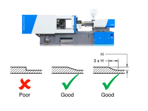
Optimization Strategies and Key Technologies
- Design for Manufacturability (DFM) in the Design Stage
- Mold Optimization Technology
Design for Manufacturability (DFM) in the Design Stage
Wall thickness uniformity
The wall thickness difference is controlled within ±10%.
And the stiffeners are added in the thick-walled area to reduce the shrinkage difference.
Such as changing the 5mm wall thickness to 3mm 2mm ribs, and the warpage amount is reduced by 40%.
Draft angle optimization
The draft angle of ABS parts ≥ 1°, and the glossy surface needs to be increased to 2°-3° to reduce the deformation caused by demoulding stress.
Tolerance grade selection
According to GB/T 14486 standard, MT5 (±0.35mm) for general parts, MT2 (±0.07mm) for high-precision medical parts.
Material Selection & Modification Filling & Reinforcement
PA6 shrinkage is reduced from 1.5% to 0.5% with 30% glass fiber, and tolerances can be tightened to ±0.1mm.
Blend material matching
Multi-material components need to match the shrinkage rate.
Such as the shrinkage difference of PC/ABS blends is controlled within 0.2% to prevent assembly gaps.
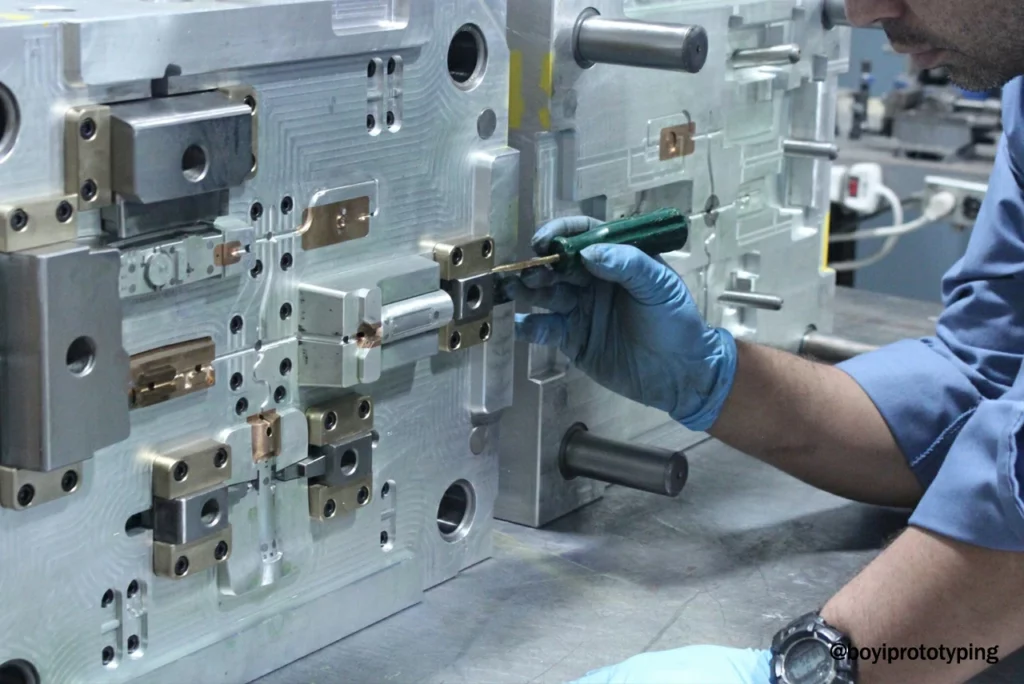
Mold Optimization Technology
Mold Flow Analysis
Use Moldflow to simulate the filling process, predict the area where the shrinkage deviation is >0.1mm,
And improve the filling uniformity by 25% after adjusting the gate position.
Insert fitting tolerance: H7/js6 transition fit, when the size is > 50mm, the fitting gap ≤ 0.02mm to prevent overflow.
Progress control
Closed-loop control: integrated pressure/temperature sensor, real-time adjustment of the holding pressure curve, so that the size fluctuation between batches <± 0.03mm.
Cooling time optimization
Calculate the cooling time (t=1.3s/mm²) according to the wall thickness.
For example, the cooling of 2mm wall thickness parts is 2.6s, which shortens the cycle and reduces deformation.