Optimization of Injection Molding TolerancesAccurate tolerances in injection molding are approached holistically by the integration of design, material selection, mold engineering, and process control.
Design, materials, molds, and process control will be discussed in detail in the overall industrial design of injection molding that is capable of effectively optimizing tolerance in injection molding as well as making sure about quality and performance.
Now, let us try to break it down-and see if there is anything in it that can strike you with sudden enlightenment.
Optimizing Injection Molding Tolerances for Precision
Various solutions to injection molding tolerances
Below is a detailed solution framework and key considerations:
- Design Optimization
- Material Considerations
- Injection Mold Engineering
- Process Control
- Cost vs. Precision Trade-offs
- Case Studies
Design Optimization
- Design for Manufacturability (DfM)
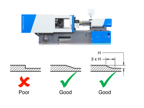
- Avoid complex geometries that induce warpage, shrinkage, or misalignment. Ensure uniform wall thickness, proper draft angles (1–3°), and rib design to minimize deformation.
- Balance functional requirements with manufacturing feasibility to reduce reliance on tight tolerances, lowering costs.
- Tolerance Specification
- Reference industry standards (e.g., DIN 16742, QC-T-29017-1991). Critical automotive parts may require stricter QC-T standards.
- Clearly define tolerance ranges in CAD files. Use relaxed tolerances (±0.2–0.5 mm) for non-critical features to save costs.
Material Considerations
- Shrinkage and Thermal Behavior
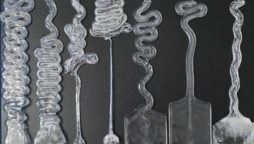
- Material shrinkage varies significantly: ABS (0.5–0.7%), PA (1.0–1.5%), and POM (1.5–2.5%). Compensate for shrinkage in mold design.
- Reinforced materials (e.g., glass-filled nylon) reduce shrinkage and improve dimensional stability (±0.1 mm achievable).
- High-Performance Materials
- For medical or aerospace components, use engineering plastics like PEEK (shrinkage ~0.1–0.3%) or LCP for tight tolerances (±0.025 mm).
Injection Mold Engineering
- Mold Precision
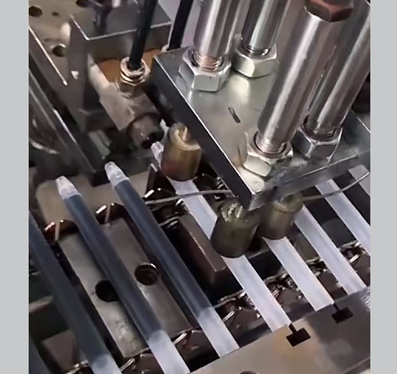
- Standard mold tolerances: ±0.127 mm (±0.005″). High-precision molds achieve ±0.025 mm (±0.001″) with CNC machining or EDM.
- For multi-cavity molds, ensure uniform cooling to prevent differential shrinkage.
- Mold Materials and Features
- Tool steel (e.g., H13) provides thermal stability for long production runs. Aluminum molds are cost-effective for prototypes.
- Integrate in-mold sensors (pressure, temperature) and interchangeable inserts for real-time process adjustments.
Process Control
- Critical Parameters
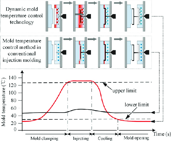
- Temperature Control: Barrel (180–300°C) and mold (20–120°C) temperatures must align with material specifications.
- Injection Pressure/Speed: Optimize via mold flow analysis (e.g., Moldflow®) to balance fill time (0.5–5 sec) and avoid defects like flash or short shots.
- Cooling Time: Longer cooling reduces warpage but increases cycle time. Use conformal cooling channels for efficiency.
- Quality Assurance
- Implement Statistical Process Control (SPC) to monitor critical dimensions (Cp/Cpk >1.33).
- For critical parts, use 100% inspection (CMM, vision systems) or X-ray/CT scans to detect internal voids or warpage.
Cost vs. Precision Trade-offs
- Tolerance Classes
- Standard tolerance (±0.1 mm): Cost-effective for most applications.
- Tight tolerance (±0.025 mm): Increases mold costs by 30–50% and requires advanced process monitoring.
- Post-Processing
- For small batches, combine relaxed tolerances with secondary machining (e.g., CNC drilling) to achieve critical dimensions.
Case Studies
- Medical Syringe Components: Achieved ±0.025 mm tolerances using PEEK, hardened steel molds, and real-time pressure monitoring.
- Automotive Connectors: Met QC-T-29017-1991 standards via multi-cavity molds (32 cavities) and SPC-controlled production.
By integrating these strategies, manufacturers can optimize injection molding tolerances while balancing precision, functionality, and cost-effectiveness. Early collaboration with mold suppliers and iterative prototyping (T0–T2 samples) are key to success.
What are the tolerances for injection molding?
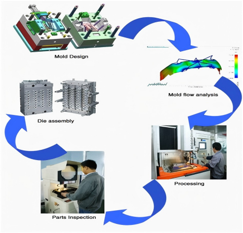
Tolerances for Injection Molding
The tolerances for injection molding vary depending on materials, part design, process control, and industry standards. Below is a detailed analysis based on comprehensive evidence:
- Typical Tolerance Ranges
- Mold Machining Tolerances
- Material and Size Impact
- Industry Standards
- Cost and Process Trade-offs
- Examples of Feature-Specific Tolerances
Typical Tolerance Ranges
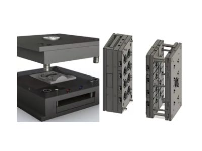
- General Applications: For most non-precision parts, the typical tolerance is ±0.1mm (≈±0.004 inches).
- High-Precision Applications: Tightened tolerances of ±0.025mm (≈±0.001 inches) or lower are achievable for critical components (e.g., medical devices or precision assemblies). For example, medical parts may require mold machining tolerances as strict as ±0.0254mm (±0.001 inches).
Mold Machining Tolerances
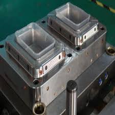
- Standard Molds: CNC machining typically achieves tolerances of ±0.127mm (±0.05 inches) for general molds.
- High-Precision Molds: Tight-tolerance molds can reach ±0.0508mm (±0.002 inches), with extreme cases (e.g., medical molds) requiring ±0.0254mm (±0.001 inches).
Material and Size Impact
- Material Shrinkage: Plastics like polypropylene (PP) and nylon (PA) have varying shrinkage rates, directly affecting dimensional accuracy.
- Part Size: Larger parts often allow looser tolerances (e.g., ±0.5mm), while smaller features can achieve tighter tolerances (e.g., ±0.125mm).
Industry Standards
- DIN 16742: The German industrial standard categorizes tolerances into fine, medium, and coarse grades, with medium tolerances suitable for most industrial parts.
- Automotive QC-T-29017-1991: Enforces stricter requirements for dimensional accuracy, shape, and surface finish to ensure assembly reliability.
Cost and Process Trade-offs
- Tight tolerances increase costs due to high-precision molds (e.g., multi-cavity molds with stable cooling systems), rigorous process controls (temperature, pressure, fill rates), and post-processing. For example, achieving ±0.025mm tolerances may lead to higher material waste and labor costs.
Examples of Feature-Specific Tolerances
- Hole Diameters: Common materials (e.g., HDPE, PP) have tolerances of ±0.15mm.
- Straightness/Flatness: Typically allowed deviations of ±0.20mm.
- Dimensional Tolerances: Base tolerances for most materials are ±0.25mm.
More we telling
Tolerances in injection molding depend on part functionality, material behavior, and cost constraints. Typical ranges are ±0.1mm, while precision applications may require ±0.025mm. Industries like automotive and medical demand stricter adherence to standards. Design optimization (via DFM, Design for Manufacturing) and collaboration with experienced suppliers are critical to ensuring tolerances are achievable and cost-effective.
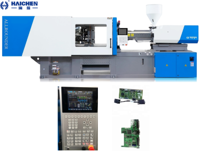
Haichen high-precision injection molding machine reduces production tolerances
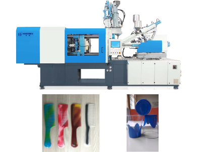
Haichen High-Precision Injection Molding Machines significantly reduce production tolerances through advanced technologies and design optimizations, specifically demonstrated in the following aspects:
- Servo Closed-Loop Control System
- Multi-Stage Pressure & Speed Control
- High-Rigidity Mechanical Structure
- Precision Temperature Control
- Intelligent Monitoring & Compensation
- Premium Hydraulic Components & Energy Efficiency
Servo Closed-Loop Control System
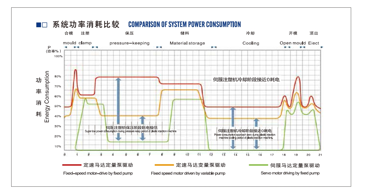
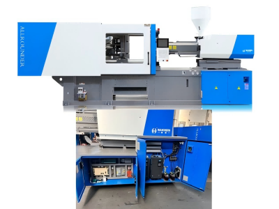
Haichen machines utilize servo motor-driven systems, employing computer and driver programs to achieve dual closed-loop control over hydraulic pressure and flow rate. This enables precise adjustment of process parameters (mold clamping, injection, packing, etc.) during molding. Compared to traditional hydraulic systems, repeat accuracy improves by 2% with faster response times, effectively minimizing tolerance variations caused by parameter fluctuations.
Multi-Stage Pressure & Speed Control
The injection unit supports multi-phase speed and pressure settings, allowing flexible switching between time-, position-, or pressure-triggered control modes. For example, segmented pressure control during packing phases prevents dimensional deviations from uneven material shrinkage. Additionally, computer-controlled multi-stage backpressure ensures consistent material plastification.
High-Rigidity Mechanical Structure
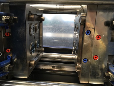
The mold clamping unit features a five-point double-toggle mechanism optimized via computer simulation, combined with hollow spherical fixed plates and box-type moving plates. This design enhances overall rigidity by 30%, maintaining stability during high-speed mold operations to prevent mechanical deformation-induced mold misalignment. Tie bars undergo specialized heat treatment, achieving industry-leading tensile strength.
Precision Temperature Control
Barrel temperatures are managed via PID closed-loop control with German Gefran position sensors, limiting temperature fluctuations to ±1°C for uniform material flow. Specialized screw options (nitrided steel, bimetal) are available for engineering plastics (e.g., PA, PC), reducing plastification inconsistencies caused by wear under high temperatures/pressures.
Intelligent Monitoring & Compensation
Equipped with special industrial computers to control machines watch important things (injection position, pressure curves) right away and have automatic fixing. For example, the injection cushion watching part automatically makes up for screw reset differences after each cycle keeping weight repeat mistakes to 0.3%. SPC data connectors allow total-process quality tracking.
Premium Hydraulic Components & Energy Efficiency
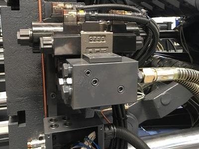
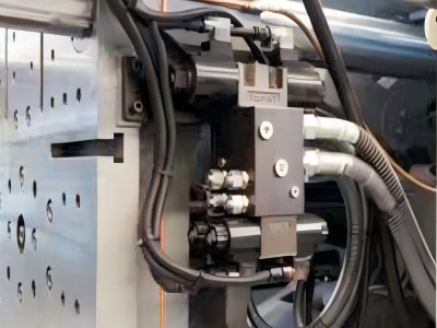
Systems use proportional valves and pumps of brands such as German Rexroth and Japanese Yuken in dual-pump high/low-pressure combinations or servo variable pumps to ensure pressure stability concurrently with energy consumption 15-70% less than that of conventional models. The fluctuation of oil temperatures that usually affect precision is minimized.

In practical applications, Haichen’s E-series servo machines achieve dimensional tolerances within MT3 class (±0.05mm) for products like electronic connectors and precision gears, with select high-precision molds reaching MT2 class (±0.02mm) to meet stringent automotive and medical industry requirements. The company also offers customized screw/barrel configurations and mold flow analysis services to further optimize process compatibility.