Injection molding feeding systems types include cold well feeding system, point gate feeding system and so on.
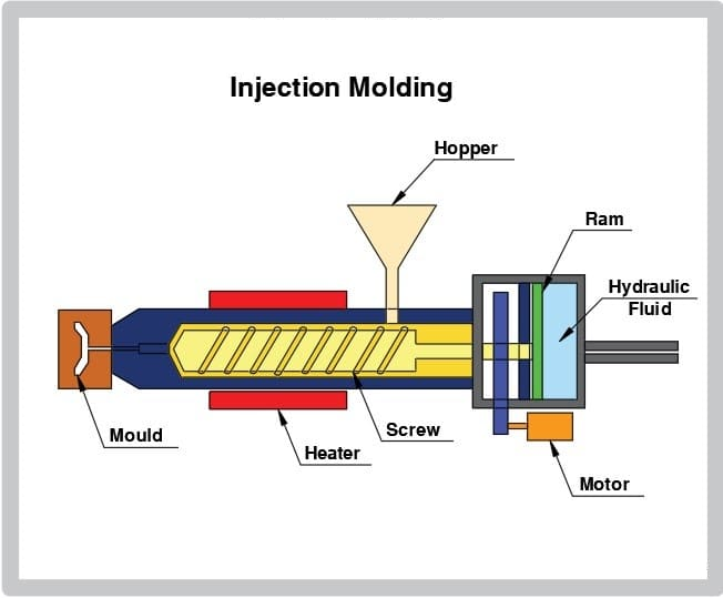
The injection molding feeding system is a comprehensive system covering raw material delivery and mold runner design. The external central feeding system realizes automation and intelligent management. The design of the mold runner system (cold/hot runner selection, geometric parameters) directly affects product quality, material utilization and production efficiency. It need optimize according to the production scale (batch/multiple varieties) and cost budget.
In injection molding, the feeding system is one of the key components. Its type and design directly affect the efficiency of the molding process and the quality of the product. According to different classification standards, the feeding system can divide into the following types:
- Cold well feeding system
- Point gate feeding system
- Hot runner feeding system
- Side gate feeding system
- Centralized feeding system
- Pneumatic suction feeding system
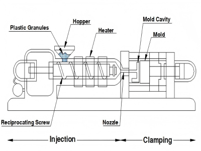
Cold well feeding system
This system feeds plastic pellets into the barrel of the injection molding machine through the cold well. And then injects them into the mold after heating and melting. Then, the cold well feeding system usually uses in the production of large injection molded parts. That can effectively control the temperature and pressure of the melt to ensure product quality.
System definition and function
- Cold runner system: It belongs to the traditional pouring system type. Which transports molten plastic from the injection molding machine nozzle to the mold cavity through a non-heated runner. The system will cool and solidify during each molding cycle and demold with the product.
- Cold Well/Cold-Slug Well: Located at the end of the runner (usually close to the gate), it uses to collect and store low-temperature materials at the front of the molten material. To prevent cold materials from entering the cavity and causing filling defects or product quality problems.
Specific functions of the cold well
- Storing the cold front material: During the injection molding process, the front of the molten material may partially solidify when it contacts the low-temperature mold. The cold well acts as a buffer to intercept this part of the low-temperature material to ensure that the subsequent high-temperature molten material evenly fills the cavity.
- Assisting flow channel balance: In multi-cavity molds, the cold well helps balance the flow of molten material in each flow channel. To ensure that all cavities fill at the same time.
- Facilitating demolding: The design of the cold well is usually conical or grooved, which facilitates the ejection system to separate the solidified flow channel material from the product.
Application scenarios and improvements
- Applicable scenarios: small and medium batch production, multi-material/multi-color products, occasions where materials are frequently changed.
- Technical improvements:
The cold well combined with the runner balance design (such as the fan-shaped gate) can optimize the filling uniformity of multi-cavity molds. - Waste recycling system: Central feeding system
Automatically recycles and processes cold runner waste, improving efficiency and reducing costs.
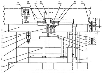
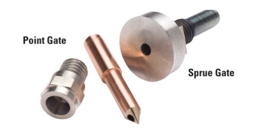
Point gate feeding system
The point gate feeding system sets one or more point gates in the mold, and the plastic melt injecte into the mold cavity through these point gates. This system is suitable for injection molded parts. Morove, it requires high precision and complex shapes. It also can reduce the number of gates and improve production efficiency.
Definition and classification of point gate
- Point gate: It also known as pin point gate, is a special type of gating system, mainly used to control the flow path and molding quality of molten plastic.
- Others: The other similar types include tunnel gate (Tunnel gate/Submarine gate) and runnerless gating.
Structure and working principle
Physical characteristics:
The point gate is a thin, conical copper gate with a very small tip size (usually about 0.5-1mm in diameter) to achieve precise flow control.
Working characteristics
When the molten plastic passes through the point gate, a high shear rate is formed, which improves the material fluidity and reduces internal defects (such as bubbles).
The key to heat transfer at the gate position: All heat is introduced into the mold through the gate cross section, resulting in an extremely thin freezing layer in this area, forming a high temperature gradient.
Hot runner feeding system of injection molding
The hot runner system uses one or more hot runner plates to transport the plastic melt from the injection molding machine nozzle to the mold cavity. This system can achieve uniform filling of multi-cavity molds and can reduce the number of gates and improve production efficiency.
Definition of hot runner system
The hot runner system is a system in the injection mold that uses an electric heating device (such as a heating rod, heating ring) to keep the plastic in the runner continuously molten, without the need to solidify the runner after each injection. Its core components include a manifold and a nozzle/drop.
Working principle of hot runner system
The molten plastic enters the manifold from the injection molding machine nozzle, and the manifold maintains a high temperature through the heater bands to distribute the plastic to each nozzle.
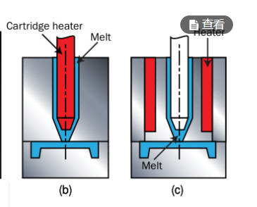
Classification by heating method
- Externally heated: The heating element is located outside the flow channel (such as the outside of the manifold) and heats the plastic through heat conduction.
- Advantages: uniform temperature distribution, suitable for heat-sensitive resins (such as PVC, POM).
- Disadvantages: high energy consumption, complex structure.
- Internally Heated: The heating element (such as a heating rod) is inserted into the center of the flow channel to directly contact the plastic.
- Advantages: High thermal efficiency, more precise control of plastic fluidity.
- Disadvantages: It is easy to cause local overheating and degradation of the material, and it is not suitable for heat-sensitive plastics.
Advantages
- Reduce waste: no solidification runner, save materials (especially expensive engineering plastics).
- Shorten cycle: no need to cool/remove the runner, improve production efficiency (suitable for large quantities).
- Improve quality:
Stable melt temperature, reduce internal stress
Valve gate can eliminate weld lines and improve appearance - Automation compatibility: no need to separate the runner and the product, simplifying the automation process.
Limitations
- High cost:Mold manufacturing cost is 30–50% higher than cold runner.
Maintenance is complex and requires professional debugging - Material limitations:
Internal heating system is not suitable for heat-sensitive resins (such as PVC)
Insulated runner is limited to semi-crystalline plastics - Process challenges:
Color change is difficult and old materials are easy to remain
High risk of drooling and clogging
Applicable scenarios
- Mass production: such as automotive parts (bumpers, interior parts), taking advantage of the efficiency of hot runners.
- Large/complex parts: multi-point injection to ensure uniform filling, valve gates to improve appearance.
- High-value materials: reduce scrap rate and raw material costs (such as medical and optical parts).
Side gate feeding system
The side gate feeding system injects the plastic melt into the mold cavity through the gate on the side of the mold. This system is suitable for the production of thin-walled injection molded parts. Moreover, it can achieve fast filling and uniform cooling.
Definition and location
- Edge gate/Side gate is one of the most common types of gates. It is usually located on the parting line of the mold (i.e. the joint surface of the two halves of the mold), and the molten plastic is injected into the cavity.
- In the classification, it belongs to the cold runner system, that is, the runner is not heated and needs to be separated from the product after each injection.
Key points of structure and design
- Dimensional parameters: gate thickness should be 50%-70% of product thickness. If it is too thin, it will cause short shot or jetting marks.
- Gate width is 1.5-2 times of thickness, and gate length (Land length) is usually designed to be about 2mm.
- Shape: Usually rectangular cross-section, pressure loss is reduced by controlling the flow path.
- Applicable scenarios: Suitable for large-area thin-walled products, can evenly fill the cavity, especially suitable for parts that require high optical transparency (such as optical parts).
Application Notes
Location selection: Avoid weld lines in the stress-bearing area, otherwise the strength of the product will be reduced.
Runner design: Multi-cavity molds must ensure that the runners are symmetrical so that the melt reaches all cavities at the same time.
Defect prevention
- Short shots or sink marks may occur if the gate size is too small.
- Thickness mutation areas need to be optimized (such as rib thickness ≤ 1/3 of wall thickness) to reduce sink marks
Centralized feeding system
The centralized feeding system feeds the raw materials into the barrel of the injection molding machine and injects them into the mold after heating and melting. This system is usually used for large-scale production and can improve production efficiency and product quality.
Pneumatic suction feeding system
This system uses a pneumatic suction device to suck plastic particles into the injection molding machine hopper and is suitable for production lines with a high degree of automation.
Therefore, these types of feeding systems have their own advantages and disadvantages. The selection of the appropriate feeding system needs to be determined based on specific production needs, product structure and process requirements.