The feed system in injection molding is a key component in the injection molding process for conveying plastic materials from the hopper to the mould cavity.
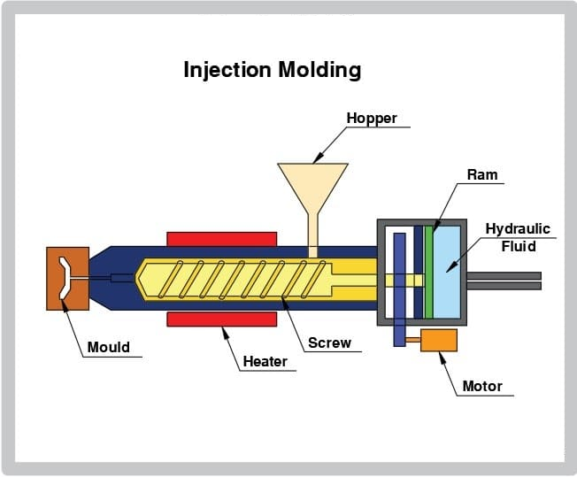
The base, barrel, hopper and clamping unit are the four basic components of the injection molding machine’s feeding system.
Each component plays an important role, including the injection molding machine’s raw material entry control and replenishment information.
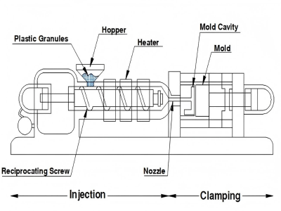
The feed system usually consists of the following main components:
Feeding system on injection molding machine
The feeding system on the injection molding machine is roughly the following five parts:
- Injection molding machine Hopper
- Feeding Mechanism
- Heating System
- Flow system (Flow System)
- Control System
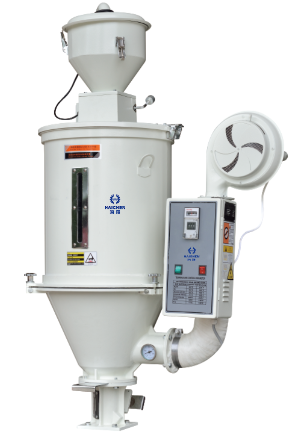
Injection molding machine Hopper
Used for storing and staging plastic materials.
The raw material enters the feeding system through the hopper.
Feeding Mechanism
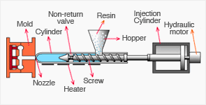
Usually consists of a screw rod or a piston, which is responsible for transporting the plastic from the hopper to the heated cylinder.
The device is capable of achieving a continuous and uniform transport of plastic into the machine.
Heating System
Located after the feeding mechanism, it is used to heat the plastic to flow state.
The heated plastic is compressed by a screw or piston and transported into the mould cavity.
Flow system (Flow System)
Includes the main flow channel, manifold and gate.
These flow channels transport the molten plastic from the nozzles of the injection machine to different areas of the mould cavity.
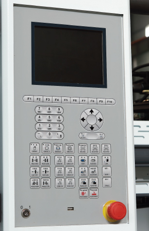
Control System
Used to regulate the feed rate and temperature to ensure that the plastic maintains proper flow during the injection process.
This improves product quality and productivity.
The design of the injection molding feed system has a significant impact on the quality of the final product.
For example, the geometry and dimensions of the runner affect the flow characteristics of the plastic.
Which in turn affects the filling effect and the quality of the finished product.
In addition, optimal design of the feeding system can reduce production costs and improve manufacturing quality and efficiency.
The feeding system is an integral part of the plastic injection molding process.
This ensuring that the plastic material is efficiently and uniformly conveyed into the mould, resulting in a high quality finished product.
Feeding System In Injection Mould
The injection molding feed system of an injection mould is a crucial part of the injection molding process.
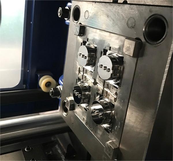
Its design and function directly affect product quality and production efficiency.
Below are some of the key features of the injection mould feeding system:
- Injection molding feed system composition
- Injection mould Runner design
- Injection Gate type
- Role of cold feed wells
- Optimisation of the feeding system
- Plastic Material flow and pressure management
- Automation and control
- Special design requirements
Injection molding feed system composition
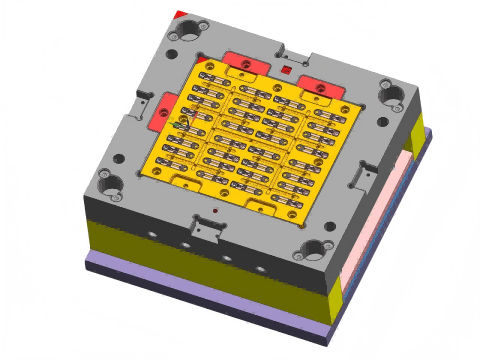
The feeding system of an injection mould usually consists of four key parts: injection port, runner, gate and cold material well.
The injection port is the starting point for the molten material to enter the mould.
While the runner is responsible for transporting the molten material from the injection port to the gate.
The gate is the channel through which the molten material enters the mould cavity.
While the cold well is used to collect the unsolidified material.
Injection mould Runner design
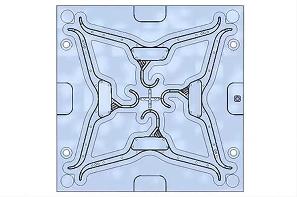
The shape and size of the runner has an important influence on the injection molding process.
Runners are usually rectangular, trapezoidal or circular in cross section.
The ideal cross-section is theoretically a rectangular cross-section, which minimises the specific surface area of the volume.
However, other shapes are more often using in practice to meet specific needs.
Injection Gate type
The design of the gate directly affects the material flow and filling.
Common gate types include wide gates, narrow gates and fan-shaped gates.
Choosing the right type of gate can effectively avoid defects such as missing material, flying edges, warpage and disintegration.
Role of cold feed wells
The main function of the cold well is to collect the material that fails to solidify during the mould filling process.
This prevents these unsolidified materials from entering the final product and affecting the quality of the product.
Optimisation of the feeding system
In modern injection mould design, we take simulation software to optimise the design of the feeding system to reduce defects and increase productivity.
For example, the use of plastic flow simulation can help to predict the flow path of molten plastic and thus optimise the feed system design.
Plastic Material flow and pressure management
The design of the feed system needs to take into account both material flow and pressure management.
For example, if the diameter of the feed opening is too small, the mould may not fill effectively.
And if the diameter is too large, it may lead to excessive pressure loss.
Automation and control
As technology develops, injection mould feed systems increasingly integrate automation and control systems.
The vision system detects the status of the raw material and then the control system commands the robotic arm to grab the raw material and place it accurately into the mould.
Special design requirements
For certain high-precision or complex shapes, in order to ensure a homogeneous flow of material without defects Haichen designs the feeding system specifically.
In some cases, lateral inlets are used to ensure that the material can fill the complex shaped mould evenly.
The feed system of an injection mould is a complex and critical component.
Its design and optimisation are essential to ensure product quality and improve productivity.
The overall performance of the injection molding process can be significantly improved through sound design and advanced technology.
What is the feed zone in injection molding?
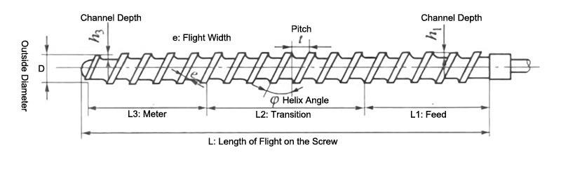
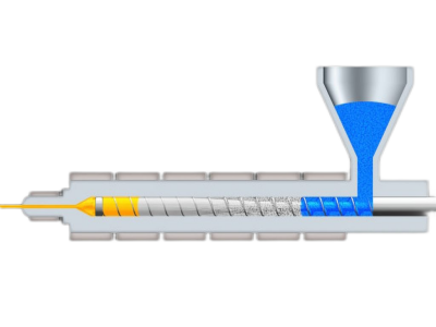
The injection feed zone is a very critical part of the injection molding process, and the feed zone usually accounts for 50% of the injection molding screw length.
The screw diameter in the compaction zone gradually increases from a small diameter in the feed zone to a large diameter in the metering zone.
Its characteristics and functions can be analysed in a number of ways:
- Structure and position of the injection molding feed zone
- Temperature control
- Material flow and mixing
- Function and role of injection molding feeding area
- Design and optimisation of the injection feed zone
Structure and position of the injection molding feed zone
The feed zone of an injection molding machine is usually located at the front end of the screw and is the first part of the material flow.
It is a small diameter zone that is primarily responsible for conveying solid plastic pellets through the screw’s rotation to the melting zone.
The length of the feed zone is typically four to five pitches to ensure sufficient pressure and thrust to convey the material.
Temperature control
The temperature in the feed zone is relatively low, usually below the melting temperature.
This is because the primary function of the feed zone is to convey the plastic pellets from the hopper to the melting zone, not to heat them.
Since the plastic pellets enter the feed zone at the right temperature, there is no need for additional heating in the feed zone.
Material flow and mixing
In the feed zone, the plastic pellets are pushed and mixed mainly by the rotation of the screw.
The rotation of the screw not only pushes the plastic granules forward, but also gradually melts and mixes them by friction and shear.
This mixing process is important to ensure that the plastic material reaches a homogeneous state before entering the melting zone.
Function and role of injection molding feeding area
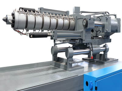
The main function of the feed zone is to convey the plastic pellets from the hopper to the melting zone.
Where they are initially mixed and heated by the rotation of the screw.
This process ensures that the plastic granules are already fluid and homogeneous before entering the melting zone.
Thus laying the foundation for the subsequent melting and injection process.
Design and optimisation of the injection feed zone
The design of the feed zone needs to take into account the geometry, pitch and speed of the screw to ensure that the plastic pellets enter the melting zone smoothly and avoid clogging or jamming.
In addition, the design of the feed zone should also take into account the characteristics of the different materials in order to optimise their flow and mixing.
The injection feed zone plays a crucial role in the injection molding process, not only in transporting the plastic pellets to the melting zone, but also in the initial mixing and heating by means of the rotation of the screw.
Proper design of the feed zone can significantly improve injection molding efficiency and product quality.

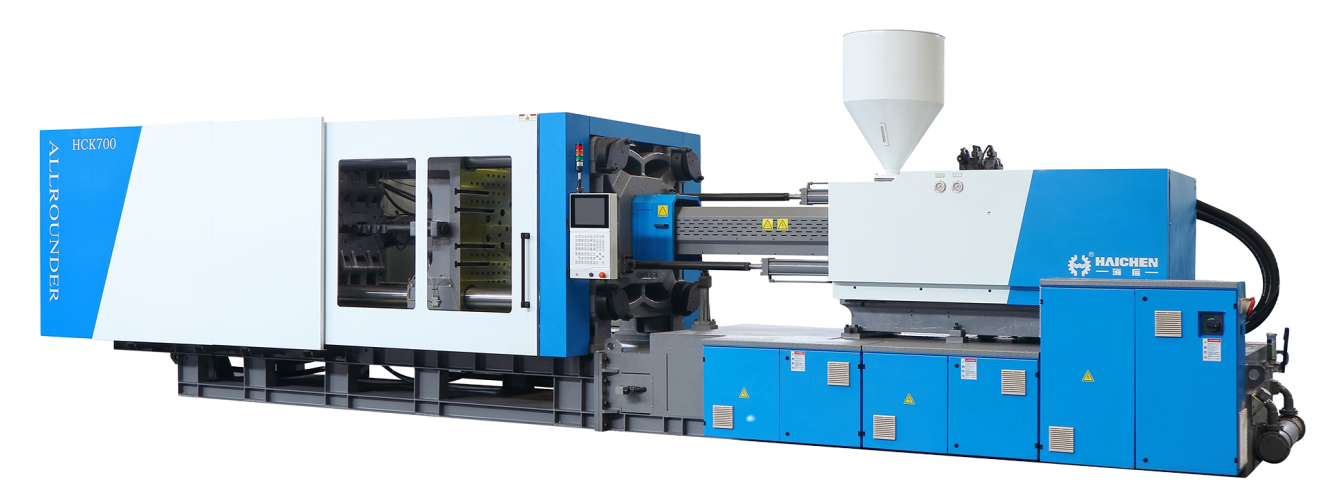
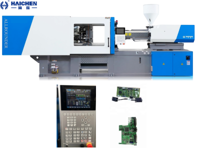
Haichen offers you high-end feeding systems for injection moulding machines.
A one-stop solution for your plastic product feeding needs for injection moulding production.
We have colour mixing, monobloc and integrated solutions for you to choose from.