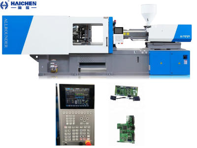
Learning how to connect a robot to an injection molding machine helps manufacturers plan a safer and more stable production process. A robot can remove molded parts, pick up runners, transfer inserts, or move parts to a conveyor. However, the robot and the injection molding machine must work together through the correct mechanical, electrical, and safety connections.
The connection involves more than plugging in a cable. First, the robot must fit the machine and mold. Next, the control interfaces must match. Finally, a qualified technician must check the signals and safety functions before production starts.
The exact process depends on the machine model, robot type, interface standard, and factory layout. Therefore, always follow the manuals from both manufacturers. This guide explains the main steps and the common problems that teams should check during installation.
What Does an Injection Molding Machine Robot Do?
An injection molding robot performs tasks around the molding cycle. It can remove finished parts from the mold and move them to another station. In addition, it can handle runners, load inserts, or place products on a conveyor.
The right robot can reduce manual handling and help keep the production cycle more consistent. However, the robot must match the product and the machine.
Common Types of Injection Molding Robots
Factories use several types of robots for injection molding.
Top-entry robots usually mount above the machine. They enter the mold area from the top and remove parts after the mold opens.
Side-entry robots approach the mold from the side. They can suit some fast-cycle applications and production layouts.
Sprue pickers remove runners or sprues from the mold. They often have a simpler task than a robot that handles finished parts.
Cartesian robots move along straight axes. They are common in injection molding because they can provide a direct path between the mold and the next station.
The best robot depends on the part size, mold layout, required movement, cycle time, and available factory space.
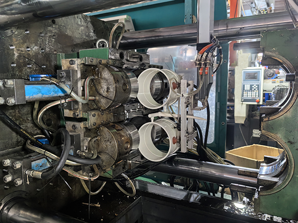
Why Connect the Robot to the Machine Controller?
The robot needs to know when it can enter the mold area and when it must wait.
Likewise, the injection molding machine needs to know whether the robot is in the correct position before it starts the next movement.
For example, the machine may need a signal showing that the robot has returned to its home position. The robot may need a signal showing that the mold has opened and the machine is ready for part removal.
These signals help the two systems follow the planned cycle. However, the exact signal names and logic vary by equipment manufacturer.
What to Check Before Connecting an Injection Molding Robot
Preparation can prevent many installation problems. Before connecting the robot, review the machine specification, robot manual, mold drawing, and intended production sequence.
Check the Machine and Robot Models
Record the full model numbers of both systems. Then ask the suppliers to confirm compatibility.
Check the following details:
- Machine model and controller
- Robot model and controller
- Robot payload and reach
- Mold dimensions
- Required part-removal path
- Electrical interface
- Required utilities
- Safety interface
- Available mounting points
Also, confirm whether the machine already has the required robot interface. Haichen’s existing robot-connection guide notes that machine mounting provisions and interface options should be confirmed with the supplier before installation.
Check the Mounting Position
The robot base must support the robot’s weight and movement loads. The mounting position must also leave enough room for the robot, gripper, mold, and finished part.
For a top-entry robot, check the available height and the support structure. For a side-entry robot, check the opening space and the path between the mold and the unloading station.
Do not drill the machine platen or change the machine structure without written approval from the machine manufacturer. Instead, use the approved mounting drawing and specified fasteners.
Confirm the Electrical Interface
The interface carries the signals between the machine and robot. However, different systems may use different connectors, signal arrangements, and communication methods.
EUROMAP 12 and EUROMAP 67 are examples of interfaces used between injection molding machines and handling devices or robots. EUROMAP 67.1 covers certain shuttle and turntable machine arrangements. The correct choice depends on the actual machine and robot. See the EUROMAP technical recommendations.
Never assume that two connectors are compatible just because they look similar. The suppliers should confirm the interface type, wiring diagram, voltage, and signal assignment.
Check the Gripper and Product
The robot needs a suitable end-of-arm tool, often called a gripper or EOAT.
The gripper must hold the part without damaging it. In addition, it must fit the mold opening and release the product in the correct position.
Before installation, check:
- Product size and weight
- Gripper shape
- Grip points
- Part release direction
- Mold clearance
- Required placement accuracy
A gripper that does not fit the part can cause dropped products, scratches, or cycle delays.
How to Connect a Robot to an Injection Molding Machine
The following steps provide a general installation sequence. They do not replace the connection drawings or commissioning procedure for a specific machine.
Step 1: Review the Drawings and Safety Instructions
First, review the machine and robot manuals. Confirm the mounting dimensions, electrical interface, signal list, and safety requirements.
Then prepare the installation plan. It should identify the people responsible for mechanical work, electrical connections, safety checks, and final approval.
Before installation or maintenance, follow the site energy-control procedure. Authorized personnel should isolate hazardous energy where required and verify the safe condition before working on the equipment.
Step 2: Install and Align the Robot Base
Use the approved mounting drawing to position the robot base or support frame.
Check that the mounting surface is suitable and that all specified fasteners are installed and tightened according to the manufacturer’s instructions.
Next, check the robot’s reach and movement path. The robot should be able to remove the part without hitting the mold, tie bars, safety guards, or nearby equipment.
Do not start automatic operation until the mounting has been inspected and approved.
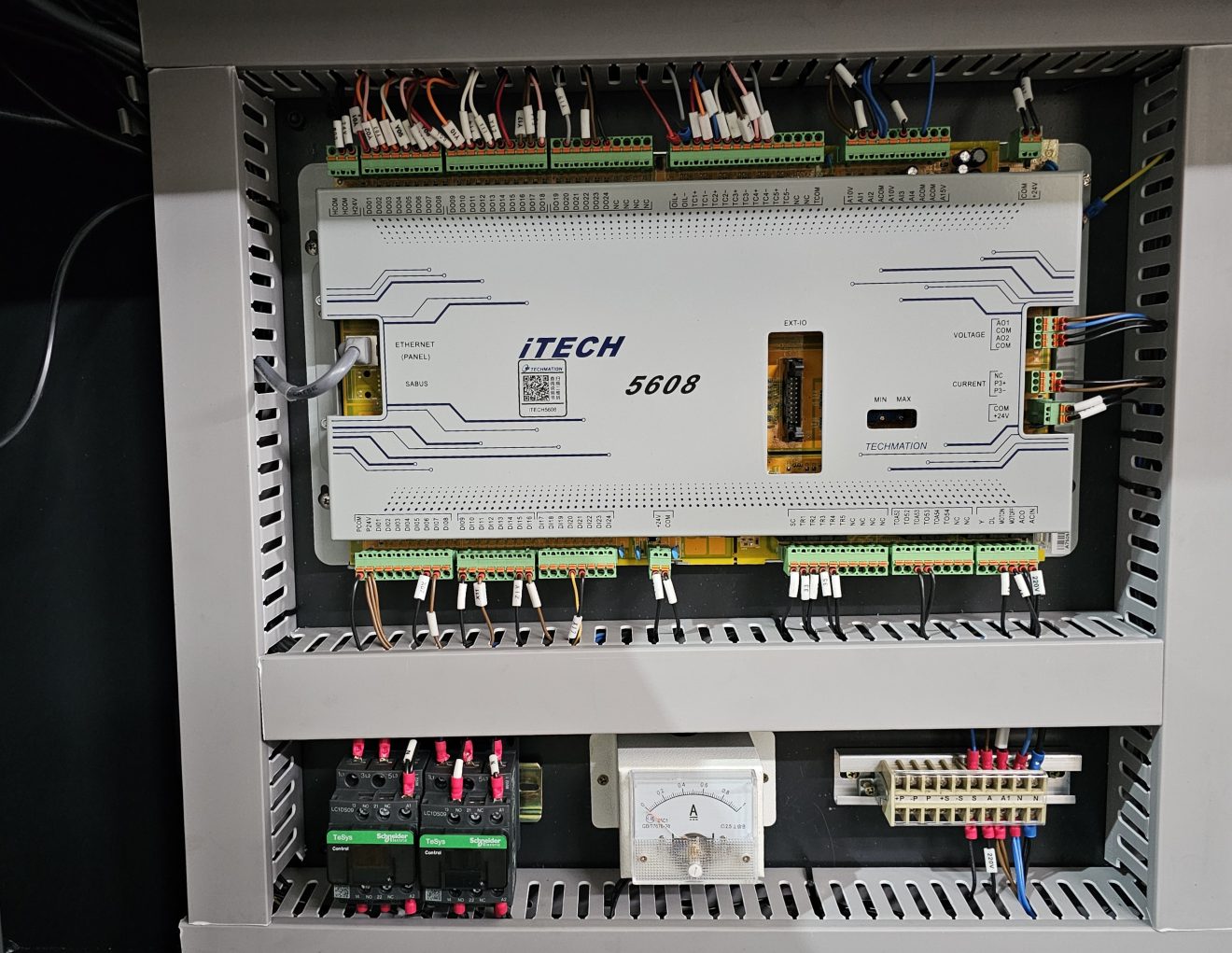
Step 3: Connect the Approved Electrical Interface
Make sure the machine and robot are in the safe state required by their manuals before authorized personnel connect the cables.
Use the specified interface and approved wiring diagram. Check connector type, cable condition, grounding requirements, and cable routing.
Keep cables away from hot surfaces, moving parts, sharp edges, and areas where the mold or robot could crush them.
Do not use improvised wiring or change signal assignments based on guesswork. If the machine and robot use different interfaces, ask the suppliers or a qualified integrator to design and approve a compatible solution.
Step 4: Connect the Required Utilities
Some robot systems require additional utilities, such as compressed air for the gripper.
Check the robot manual for the required pressure, flow, connectors, and air-quality conditions. If the system uses electric grippers or other devices, follow their specifications instead.
Route all hoses and cables so that they cannot become trapped during robot movement or mold opening.
Step 5: Check the Machine and Robot Signals
Once the connections are complete, a qualified technician should verify the signal mapping according to both manuals.
The signals may include:
- Machine ready
- Mold open
- Robot in home position
- Part removal request
- Robot cycle active
- Robot fault
- Safety status
- Cycle complete
The exact signal list will vary. Some systems use a dedicated electrical interface; others may exchange process data through a communication system.
EUROMAP 79, for example, describes OPC UA-based data exchange between injection molding machines and robots. It should not be treated as a replacement for the required safety interface. See the EUROMAP technical recommendations.
Step 6: Verify Safety Interlocks
The robot and injection molding machine must follow the approved safety design.
Before automatic production, the commissioning team should verify that required guards, interlocks, emergency-stop functions, and safety signals operate as specified.
Do not bypass a safety door switch, short a safety signal, or defeat an interlock to make the machine run. If a safety signal does not work, stop the commissioning process and ask a qualified technician to find the cause.
For more information, see Haichen’s injection molding machine safety guide.
Step 7: Run an Approved Commissioning Test
After mechanical and electrical checks pass, the authorized commissioning team can follow the manufacturer’s test procedure.
Start with the approved setup or commissioning mode. Confirm that the machine and robot follow the intended sequence and that the robot can reach the required positions without collision.
The team should check:
- Mold opening and robot access
- Robot entry and withdrawal
- Gripper operation
- Part removal
- Robot return to home position
- Machine readiness for the next cycle
- Safety system response
Use the speed and operating mode specified by the commissioning procedure. Keep people outside hazardous areas and do not enter the mold space while the system can move.
Step 8: Confirm the Complete Production Cycle
Once the individual movements work correctly, the team can check the complete sequence under the approved test conditions.
The robot should remove the part, move to the intended unloading position, release the part, and return to its required position. The machine and robot must remain synchronized throughout the cycle.
Then inspect sample parts for scratches, deformation, dropped parts, or other handling defects.
Record the final settings, test results, and any approved changes. Before routine production, the responsible team should sign off the installation according to the site’s procedures.
Common Problems When Connecting an Injection Molding Robot
The Robot Does Not Receive the Machine Signal
First, check the selected interface, connectors, and signal configuration against the approved drawings. Also, check for alarms on the machine and robot controllers.
Do not change wiring without confirming the correct signal assignment.
The Robot Cannot Reach the Mold
The problem may come from the mounting position, robot reach, gripper size, or mold layout.
Review the machine drawing and robot work envelope. Then adjust the mounting or tooling only under an approved engineering plan.
The Machine and Robot Do Not Follow the Same Cycle
This problem may come from incorrect signal mapping, unsuitable timing, or a robot sequence that does not match the machine cycle.
Review the control sequence with the integrator. Confirm that each required signal is sent and received at the correct stage.
The Robot Drops or Damages the Part
The gripper may not suit the product shape, material, or weight. It may also release the part before reaching the correct position.
Check the gripper design, gripping force, product contact points, and release sequence. Then test the approved solution under controlled conditions.
A Safety Signal Does Not Work
Stop the commissioning process. Do not bypass the signal to continue the test.
A qualified technician should check the wiring, device condition, and safety logic against the approved drawings. The machine should return to production only after the fault is corrected and the required verification is complete.
How Robot Integration Improves Injection Molding Production
When the machine, mold, robot, and conveyor work together, automation can reduce repeated manual handling.
A robot may help to:
- Remove parts at a steady point in the cycle
- Reduce direct operator contact with hot parts
- Transfer products to a conveyor
- Handle runners or inserts
- Support automatic counting or packing
- Keep the production sequence consistent
However, automation alone does not guarantee shorter cycle time. The robot must finish its movement within the available cycle, and the mold, cooling, and downstream handling must also support the target output.
For this reason, measure the complete cycle rather than looking at robot speed alone.
What Information Do You Need for Robot Integration Support?
When asking Haichen or another machine supplier for integration support, provide:
- Injection molding machine model
- Robot brand and model
- Machine controller model
- Robot interface type
- Mold dimensions
- Part weight and shape
- Gripper requirements
- Target cycle time
- Auxiliary equipment list
- Factory safety requirements
These details help the supplier confirm whether the current interface and mounting arrangement suit the project.
Frequently Asked Questions
Can Any Robot Connect to Any Injection Molding Machine?
No. The machine and robot need compatible mounting, control interfaces, signals, and safety functions. A qualified supplier or integrator should check compatibility before installation.
What Is EUROMAP 67?
EUROMAP 67 is an electrical interface specification for communication between an injection molding machine and a handling device or robot. The actual interface needed depends on the machine, robot, and application.
Does a Robot Reduce Injection Molding Cycle Time?
It can reduce handling time and make part removal more consistent. However, the result depends on robot movement, mold design, cooling time, and the complete production sequence.
Can I Connect the Robot by Matching the Wire Colors?
No. Wire colors alone do not confirm the signal, voltage, or interface. Use the approved wiring diagram and have qualified personnel complete the electrical work.
What Should I Do If the Robot Does Not Respond?
Stop the commissioning test and check the machine and robot alarms. Then have a qualified technician inspect the interface, signal configuration, and approved connection drawings.
Plan Your Injection Molding Robot Integration
Send Haichen your machine model, robot model, mold information, interface details, and production target. With these details, the team can review the mounting arrangement, interface compatibility, and automation requirements for your project.
For related safety information, read How to Test an Emergency Stop on an Injection Molding Machine.
Haichen Yang
Author: Yang, Senior Engineer, Haichen Machinery